Multi-target measurement and control ground station system

A multi-target, ground station technology, applied in the field of multi-target measurement and control ground station system, can solve the requirement of simultaneous tracking and receiving multiple target telemetry signals by a single antenna, increase the number of cable connections, and network high-precision timing is difficult to achieve High-gain antennas and other issues can achieve high isolation, reduce the number of cables, and simplify system design

Active Publication Date: 2022-03-29
CHENGDU FOURIER ELECTRONICS TECH +1
View PDF9 Cites 0 Cited by
  • Summary
  • Abstract
  • Description
  • Claims
  • Application Information

AI Technical Summary

Problems solved by technology

To increase the gain of an omnidirectional array antenna, the antenna area and the number of feed elements will increase exponentially. It is difficult to achieve a high-gain antenna in engineering, and the application range is greatly limited.
[0004] CN104459687A discloses a multi-target vehicle-mounted measurement and control system based on a flat-panel self-tracking antenna. The system uses a flat-panel antenna to correspond to a target through a flat-panel antenna, which belongs to the mechanical tracking mode. It is necessary to set a plurality of flat-panel correspondingly to realize multi-target tracking. In essence, multiple traditional mechanical tracking antennas are integrated into one chassis to achieve multi-target tracking, which does not meet the requirements of a single antenna for simultaneously tracking and receiving multiple target telemetry signals
Moreover, because the existing telemetry method adopts the IRIG-B code timing, there is a problem that the number of cable connections and the high-precision timing of the network will increase significantly with the increase in the number of devices.

Method used


Image

  • Multi-target measurement and control ground station system
  • Multi-target measurement and control ground station system
  • Multi-target measurement and control ground station system

Examples


Embodiment

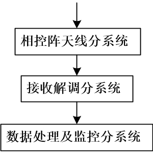
[0074] Such as figure 1 Shown is the structure diagram of the multi-target measurement and control ground station system in this example.

[0075] The system includes: phased array antenna subsystem, receiving demodulation subsystem, data processing and monitoring subsystem and vehicle body.

[0076] The phased array antenna subsystem, receiving demodulation subsystem, data processing and monitoring subsystem are all integrated in the vehicle body.

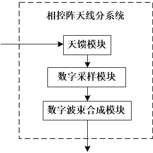
[0077] Specifically, in this example, the phased array antenna subsystem adopts the following figure 2 The structural composition shown includes an antenna feeder module, a digital acquisition module, and a digital beamforming module.

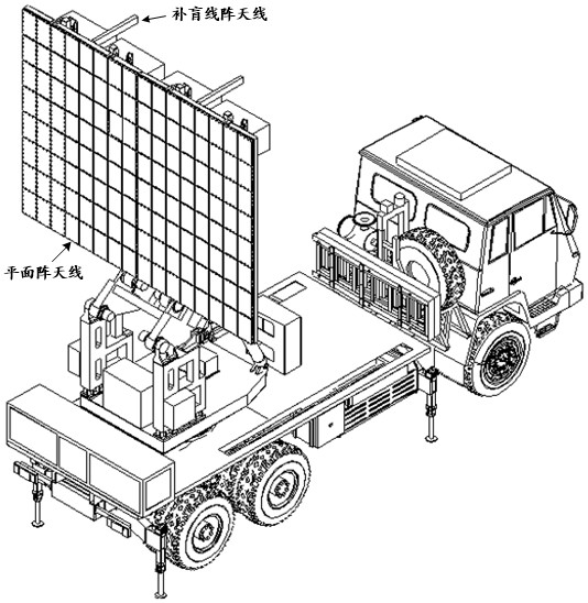
[0078] The antenna feeder module includes multiple digital-analog mixed planar array antennas, and a blind-filling linear array antenna used in conjunction with the planar array antennas to receive space signals in the airspace range of 0°~90° elevation and output multiple radio frequency signal...


PUM


Abstract

Multi-target measurement and control ground station system, including phased array antenna subsystem, receiving demodulation subsystem, data processing and monitoring subsystem. The phased array antenna subsystem includes: Antenna feeder module, including planar array antenna and blind line array antenna; digital acquisition module, which performs power division, filtering, amplification, down-conversion, and AD acquisition digitization of multi-channel radio frequency signals; digital beamforming The module receives multiple digitized target signals and performs digital beamforming, and each target corresponds to forming a digital beam signal; the receiving demodulation subsystem includes multiple receiving demodulation modules, which receive and demodulate multiple digital beam signals; The data processing and monitoring subsystem performs unified network time service and real-time monitoring of other equipment in the system. Meet the measurement and control requirements of multiple large airspace aircraft and long-distance spaceflight targets, solve intermodulation and intermodulation interference and ENOB compression problems when multiple targets are located at different distances, improve timing accuracy, and improve system integration.

Description

technical field [0001] The invention belongs to the field of communication, relates to multi-target remote measurement / measurement and control, and in particular relates to a multi-target measurement and control ground station system. Background technique [0002] With the rapid development of weapons and equipment and the improvement of the actual combat requirements of test tasks, the traditional single-engine single-engine target shooting test has changed to multi-machine cooperative formation and multi-engine confrontation test tasks. There is an increasingly urgent need for simultaneous multi-target tracking capabilities of telemetry systems. The telemetry system used in the flight test is a large airspace and broadband wireless transmission system, which has high requirements for link gain. At the same time, the equivalent radiation power of the airborne and missile-borne launch systems is limited by the transmit power and antenna aperture. It is limited to a small ran...

Claims


Application Information

Patent Timeline
Patent Type & Authority Patents(China)
IPC IPC(8): H04Q9/00H04Q9/04H04J3/06H04L41/0213H04B7/06G08C17/02G08C23/06
CPCH04Q9/00H04Q9/04H04J3/0644H04J3/0667H04L41/0213H04B7/0617G08C17/02G08C23/06H04Q2209/20H04Q2209/40
Inventor 吕春
Owner CHENGDU FOURIER ELECTRONICS TECH
Why Eureka
Try Eureka