Gas concentration detection apparatus

A technology for gas concentration detection and equipment, applied in mechanical equipment, electrical control, measuring devices, etc., to achieve high accuracy

Inactive Publication Date: 2014-02-19
TOYOTA JIDOSHA KK
View PDF13 Cites 0 Cited by
  • Summary
  • Abstract
  • Description
  • Claims
  • Application Information

AI Technical Summary

Problems solved by technology

The apparatus disclosed in Patent Document 2 makes it possible to maintain a desired element temperature by correcting the target value of the element resistance according to the heater power

Method used


Image

  • Gas concentration detection apparatus
  • Gas concentration detection apparatus
  • Gas concentration detection apparatus

Examples


no. 1 approach

[0102] [Structure of the first embodiment]

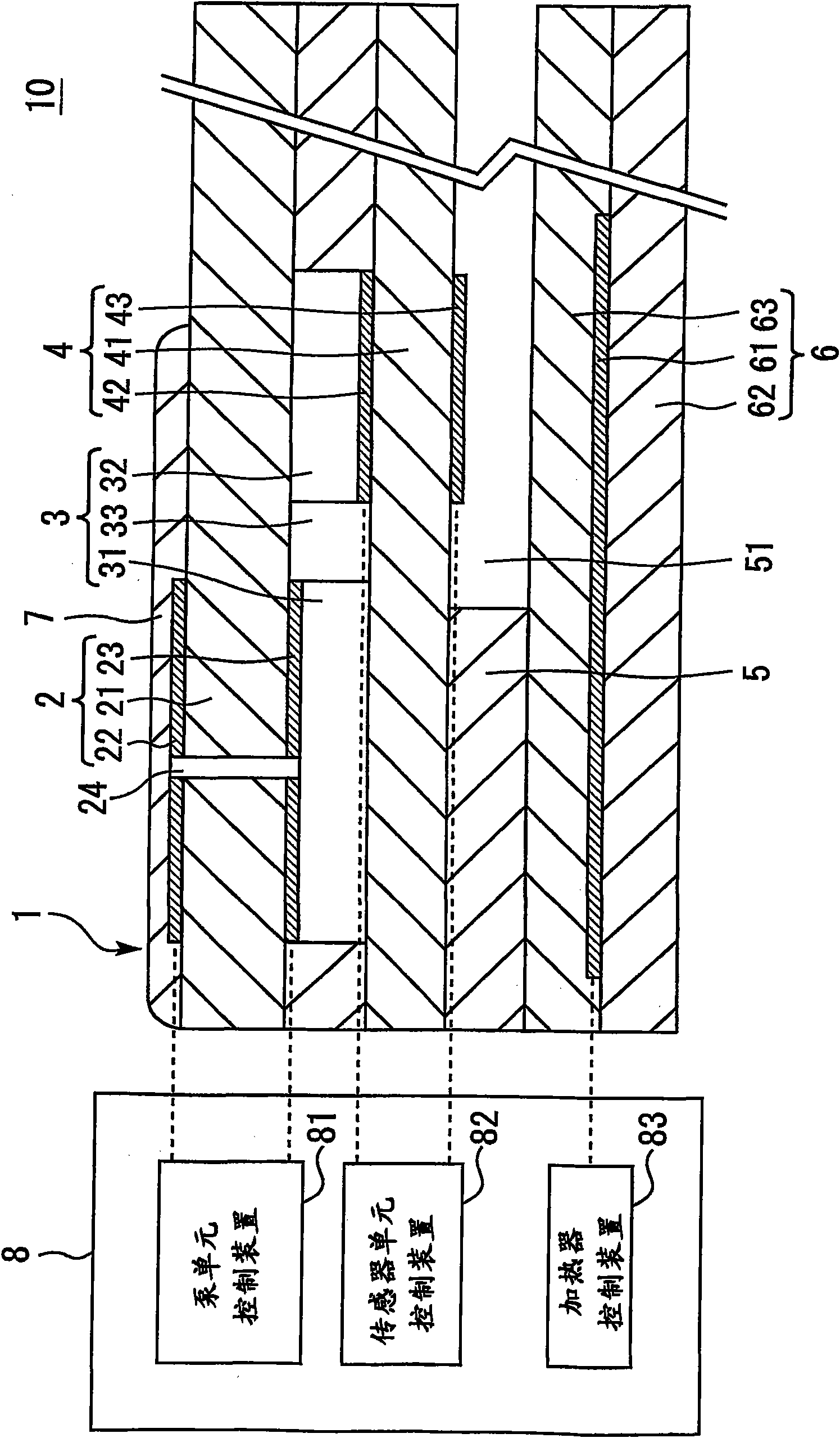
[0103] First, refer to figure 1 The configuration of the gas concentration detecting device according to the first embodiment of the present invention will be described. figure 1 is a diagram illustrating the configuration of the gas concentration detection device 10 according to the first embodiment. figure 1 The shown gas concentration detecting device 10 is a NOx concentration detecting device which detects, for example, nitrogen oxides (NO X )concentration.

[0104] The gas concentration detection device 10 includes a NOx sensor 1 . The NOx sensor 1 is formed by sequentially stacking a spacer 3 , a NOx sensor unit 4 , another spacer 5 , and a heater 6 below the oxygen pump unit 2 .

[0105] The oxygen pump unit 2 is capable of removing excess oxygen from a measurement target gas, and includes a solid electrolyte body 21 , a first pump electrode 22 , and a second pump electrode 23 . The solid electrolyte body 21 is sandwiche...

no. 2 approach

[0155] will now refer to Figure 7 to Figure 9 A second embodiment of the present invention will be described. when using figure 1 The hardware configuration shown enables the ECU 8 to perform Figure 9 When the program described later is shown, the gas concentration detecting device according to the second embodiment is realized.

[0156] [Features of the second embodiment]

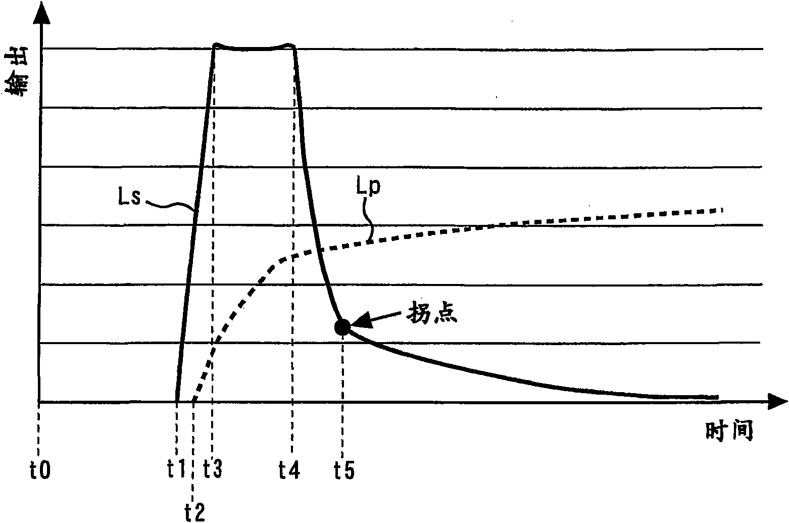
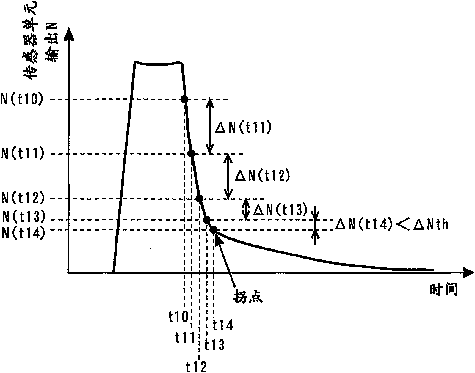
[0157] The first embodiment described earlier locates an inflection point based on, for example, a comparison between the NOx sensor cell output change amount ΔN(t) and a reference value ΔNth, and forms an activity judgment about the NOx sensor 1 when the inflection point occurs.

[0158] Meanwhile, the oxygen pump unit 2 is configured the same as the NOx sensor unit 4 . The output of these cells is in the oxygen ion O 2- The value of current they have when flowing into them. Therefore, there is a correlation between the oxygen pump cell output and the NOx sensor cell output. The second embodiment...

no. 3 approach

[0182] will now refer to Figure 12A with Figure 12B A third embodiment of the present invention will be described. The first embodiment described earlier forms an activity judgment about the NOx sensor 1 when an inflection point occurs in the output of the NOx sensor cell. Therefore, it should be preferable to obtain the NOx sensor cell output whose inflection point can be easily located.

[0183] Therefore, the third embodiment will be described with specific reference to the configuration of the NOx sensor 1 that makes it easy to locate the inflection point in the output of the NOx sensor cell. Figure 12A with Figure 12B is a diagram illustrating the configuration of the NOx sensor 1 according to the third embodiment. More specifically, Figure 12A is a cross-sectional view of NOx sensor 1, and Figure 12B is a plan view of the heater electrode 61 in the NOx sensor 1 .

[0184] Such as Figure 12B As shown, the width W1 of the heater electrode 61 on the side faci...


PUM


Abstract

It is an object of the present invention to provide a gas concentration detection apparatus that is capable of forming an accurate activity judgment when a gas concentration detection cell begins to detect gas concentration with high accuracy. When warm-up begins at time t0 in a NOx concentration detection apparatus that achieves NOx concentration detection with a NOx sensor cell after excess oxygen is discharged by an oxygen pump cell, a NOx sensor cell output begins to rise at time t1. Subsequently, at time t2, an oxygen pump cell output begins to rise. An inflection point appearing in the NOx sensor cell output is then located. At time t5 at which the inflection point appears, an activity judgment about the NOx sensor cell is formed.

Description

technical field [0001] The present invention relates to a gas concentration detection device, and more particularly, to a gas concentration detection device that detects the concentration of a specific gas component in exhaust gas discharged from an engine. Background technique [0002] There is a known gas concentration detecting device having an oxygen pump unit for exhausting excess oxygen and a sensor unit for detecting a specified component in the gas from which excess oxygen is exhausted concentration (for example, refer to Patent Document 1). The gas concentration detecting device disclosed in Patent Document 1 corrects the value of the current flowing into the sensor unit according to the value of the current flowing into the oxygen pump. This makes it possible to achieve highly accurate concentration detection even when the oxygen concentration in the detection target gas changes. [0003] The oxygen pump unit and the sensor unit each include an element made of a ...

Claims


Application Information

Patent Timeline
Patent Type & Authority Patents(China)
IPC IPC(8): G01N27/407G01N27/406F02D41/06F02D41/12
CPCF02D41/06G01N27/4067G01N27/419F02D41/123
Inventor 佐佐木敬规
Owner TOYOTA JIDOSHA KK
Why Eureka
Try Eureka