
Detecting device for scene space lighting

A detection device and space technology, applied in the direction of color measurement device, using electric radiation detector for photometry, using electric radiation detector for color measurement, etc., can solve the problems of affecting measurement accuracy, single function, and time-consuming measurement, etc. Achieve the effect of improving measurement accuracy, high measurement accuracy, and high signal-to-noise ratio

Active Publication Date: 2013-05-22
ZHEJIANG SANXIN LIGHTING INSPECTION EQUIP
View PDF4 Cites 4 Cited by
  • Summary
  • Abstract
  • Description
  • Claims
  • Application Information

AI Technical Summary

Problems solved by technology

[0005] 2. Time-consuming measurement, poor position and direction positioning
To measure point by point on site requires constant repositioning, and when measuring on different vertical planes, reorientation is also required. Therefore, the measurement is time-consuming and the positioning error is large;
[0006] 3. Single function and time-consuming
When testing multiple indicators, different testing equipment is required, which not only wastes the measurement time, but also increases the cost;
[0007] 4. Measuring personnel intervene in the scene, affecting the measurement accuracy
Traditional measurement equipment requires operators, computers and other auxiliary equipment to intervene in the measurement site, which will damage the lighting environment of the measurement site and affect the measurement accuracy
[0008] The above defects have seriously affected the efficiency and accuracy of photoelectric detection in lighting environments

Method used


Image

  • Detecting device for scene space lighting
  • Detecting device for scene space lighting
  • Detecting device for scene space lighting

Examples


Embodiment Construction

[0024] The present invention will be further described below with reference to the accompanying drawings.

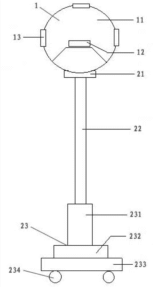
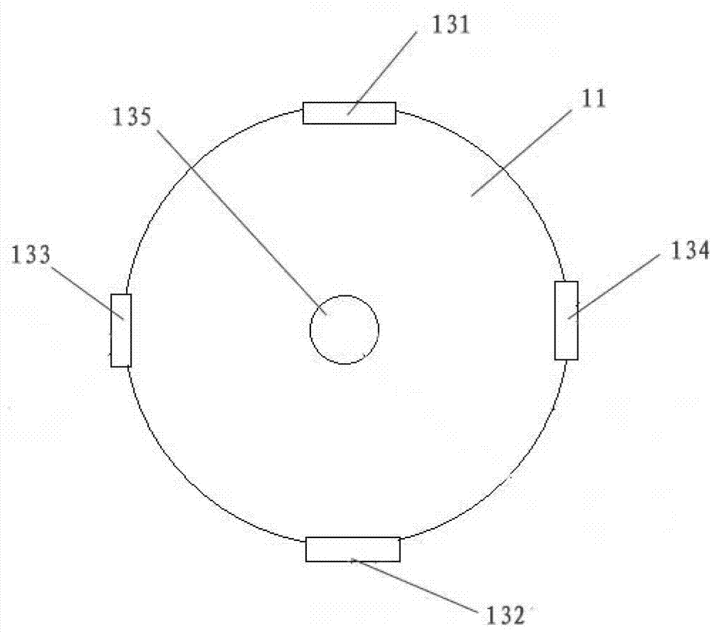
[0025] Such as Figure 1-Figure 3 As shown, an on-site space lighting detection device described in this embodiment includes a photoelectric detection head 1, a mobile platform 2 and a data recording device. The photoelectric detection head 1 is fixed on the movable platform 2 that can be displaced, and the described The photoelectric detection head 1 includes a housing 11 and a plurality of detectors 13 arranged on the housing, and the detectors 13 include a front detector 131, a rear detector 132, a left detector 133, a right detector 134 and an upper detector 135, respectively arranged in the front, rear, left, right and upper part of the housing, the light receiving surfaces of the front detector 131 and the rear detector 132 are parallel to each other, the light from the left detector 133 and the right detector 134 The receiving surfaces are parallel to each other,...


PUM


Abstract

The invention provides a detecting device for scene space lighting. The detecting device for the scene space lighting solves the technical problem that efficiency and precision of the photoelectric detection of the current luminous environment are low. The detecting device for the scene space lighting comprises a photoelectric detecting head, a mobile platform and a data recording device. The detecting device for the scene space lighting is characterized in that the photoelectric detecting head is fixed on the mobile platform which can be displaced; the photoelectric detecting head comprises a shell and a plurality of detecters which are arranged the shell; the detecter comprises a front detector, a rear detector, a left detector, a right detector and an upper detector, wherein the detector, the rear detector, the left detector, the right detector and the upper detector are respectively arranged at the front portion, the rear portion, the left portion,the right portion and the upper portion. The front detector and the rear detector, the left detector and the right detector are mutually perpendicular to the light receiving surface of the upper detector. The detecting device for the scene space lighting has an integrated function capable of measuring five directions and can measure light distributions of the space of the environment. The mobile device which can be operated flexibly, conveniently and fast enables the detecting device to be placed in different working environments, so that the scene can be measured conveniently and randomly.

Description

technical field [0001] The invention relates to the field of photoelectric detection of lighting environment, in particular to an on-site space lighting detection device. Background technique [0002] With the rapid development of my country's economy and the improvement of the quality of life, people pay more and more attention to the improvement of lighting quality. Especially with the increase of my country's comprehensive national strength, its influence in the world has gradually increased, and more and more sports events are held in my country. World-class sports events have high requirements on the lighting conditions of venues and venues, not only for traditional detection indicators such as illuminance, brightness, glare, etc., but also for the uniformity of spatial luminosity and chromaticity distribution of venues and venues. high demands. The acceptance and inspection of the lighting environment of these venues and venues has become a difficult problem for phot...

Claims


Application Information

Patent Timeline
Patent Type & Authority Applications(China)
IPC IPC(8): G01J1/42G01J3/28G01J3/50
Inventor 王建平徐明明
Owner ZHEJIANG SANXIN LIGHTING INSPECTION EQUIP
Learn More