Falling film scraper type multi-pipe evaporation and concentration device

An evaporative concentration and scraper-type technology, which is applied in the direction of evaporation, chemical instruments and methods, and separation methods, can solve problems such as unfavorable saving of steam and electric energy consumption, increased difficulty of equipment management and maintenance, and increased equipment investment, so as to reduce equipment Quantity, save manpower input, increase the effect of heat exchange area

Inactive Publication Date: 2013-05-29
常熟市龙宇化工设备有限公司
View PDF11 Cites 5 Cited by
  • Summary
  • Abstract
  • Description
  • Claims
  • Application Information

AI Technical Summary

Problems solved by technology

[0003] However, it is not limited to the following disadvantages in the patent schemes listed above: First, because the heat exchange area is difficult or even impossible to expand under the premise of the same diameter of the cylinder body (usually called the concentration tank body), it can only be increased by increasing the equipment. However, increasing the number of concentrators will not only lead to a large investment in equipment, but also increase the number of operators, and increasing the volume of the cylinder will also increase the investment in equipment, and the pipes of the equipment will also increase. The difficulty of maintenance also increases accordingly. In addition, whether it is to increase the number or increase the volume of the enrichment device, it is not conducive to saving steel resources; second, in order to ensure the concentration efficiency of the material per unit time, the concentration device cannot be designed to be miniaturized. Thereby be unfavorable for saving steam and electric energy consumption; The 3rd, owing to comprise the known technology of above-mentioned patent, the heat exchange area of ​​concentrator is usually less than 20 square meters, and if want to make heat exchange area reach 40, 60 or 80 square meters or even larger, currently the industry can only meet the requirements by increasing the number of enrichment devices

Method used


Image

  • Falling film scraper type multi-pipe evaporation and concentration device
  • Falling film scraper type multi-pipe evaporation and concentration device

Examples


Embodiment 1

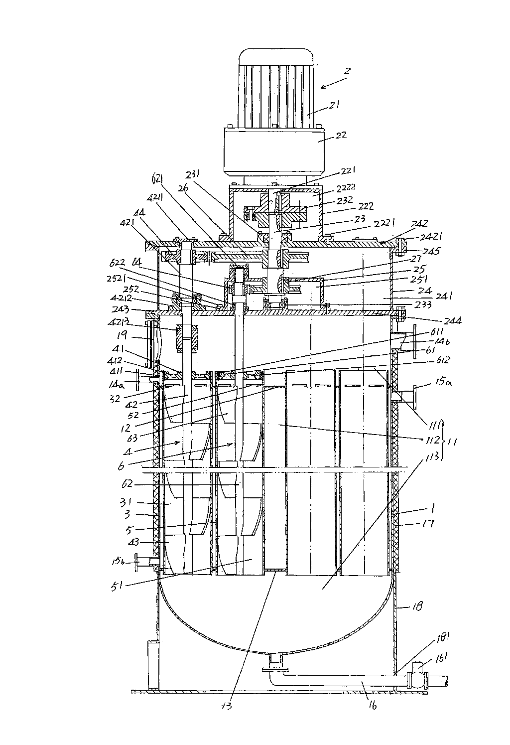
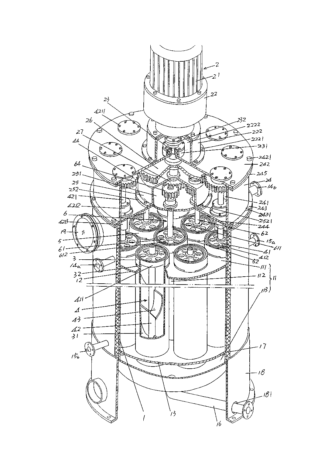
[0021] See figure 1 and figure 2, a cylindrical concentration tank body 1 is given, an upper sealing plate 12 is fixed in the tank cavity 11 of the concentration tank body 1 and is located at the upper part of the height direction of the tank cavity 11, and the tank cavity 11 A lower sealing plate 13 is fixed near the bottom. As shown in the figure, the height direction of the tank cavity 11 is divided into a distribution cavity 111 (also called a feeding cavity), a steam heating cavity 112 and a discharge cavity by the aforementioned upper sealing plate 12 and lower sealing plate 13. 113 , more precisely: the material distribution chamber 111 is located above the upper sealing plate 12 , the steam heating chamber 112 is located between the upper and lower sealing plates 12 and 13 , and the discharge chamber 113 is located below the lower sealing plate 13 .

[0022] On the side wall of the concentration tank body 1 and at a position corresponding to the aforementioned distr...

Embodiment 2

[0038] The figure is omitted, only the number of one group of peripheral concentrator cylinders 3 is changed to six, and the corresponding number of first scraping film mechanisms 4 is also six; the number of central concentration cylinders 5 is changed to one, and the corresponding second wiper film The number of mechanisms 6 is also one. All the other are the same as the description to embodiment 1.

[0039] applicant combined figure 1 and figure 2 And describe the working process of the present invention according to the explanation of embodiment 1. The high-temperature steam generated by a steam source such as a boiler is introduced into the steam heating chamber 112 of the tank chamber 11 through the steam inlet port 15a through the pipeline, and at the same time, the material to be concentrated is introduced into the material distribution chamber 111 through the feed port 14a through the pipeline. Because the peripheral concentrating cylinder chamber 31 of one group ...


PUM


Abstract

The invention discloses a falling film scraper type multi-pipe evaporation and concentration device belonging to the technical field of biological medicine chemical equipment. The evaporation and concentration device comprises a concentration tank body, a power transmission mechanism, a group of periphery concentration tubes and one or more than one centre concentration tube, wherein a tank cavity of the concentration tank body is internally provided with upper and lower sealing plates; the upper and lower sealing plates are used for dividing the tank cavity into a cloth cavity, a steam heating cavity and a discharging cavity; the power transmission mechanism is arranged on the top of the concentration tank body; the periphery concentration tubes are arranged by surrounding the peripheral direction of the steam heating cavity, the upper end of each periphery concentration tube and the upper sealing plate are fixed and the upper end of each periphery concentration tube can extend in the cloth cavity, the lower end of each periphery concentration tube and the lower sealing plate are fixed, and periphery concentration tube cavities are internally provided with a first knifing mechanism which is in transmission connection with the power transmission mechanism; and the upper end of the centre concentration tube and the upper sealing plate are fixed and the upper end of the centre concentration tube can extend in the cloth cavity, the lower end of the centre concentration tube and the lower sealing plate are fixed, and a centre concentration tube cavity is internally provided with a second knifing mechanism which is in transmission connection with the power transmission mechanism. The falling film scraper type multi-pipe evaporation and concentration device provided by the invention has the advantages that the effective heat exchange area of the concentration tank body is notably increased under the condition of the concentration tank boy with same volume.

Description

technical field [0001] The invention belongs to the technical field of biomedicine and chemical equipment, and in particular relates to a falling film scraper type multi-tube evaporation and concentration device. Background technique [0002] The aforementioned falling film scraper type multi-tube evaporation and concentration device belongs to the category of falling film thin film evaporators, and is widely used in the production industries such as biomedicine, chemical industry and even food additives. For example, the authorized announcement number CN2125439U recommends a "plate-type heating falling film evaporator". This patent solution is to replace the seamless steel pipe in the prior art by a group of hollow thin plates arranged in the cylinder. Each hollow thin plate has a capacity of Cavity, and is equipped with steam inlet pipe and condensate discharge outlet. According to the analysis of the last paragraph of the second page of the patent specification text to ...

Claims


Application Information

Patent Timeline
Patent Type & Authority Applications(China)
IPC IPC(8): B01D1/22
Inventor 吕鸣冈张建龙
Owner 常熟市龙宇化工设备有限公司
Why Eureka
Try Eureka