
Plate-fin heat exchanger having application to air separation

a heat exchanger and plate-fin technology, which is applied in indirect heat exchangers, lighting and heating apparatuses, laminated elements, etc., can solve the problems of increasing surface area inevitably at the expense of more frictional pressure drop, reducing heat exchange duty, and reducing heat exchange efficiency. , to achieve the effect of preventing an excessive pressure drop, reducing frictional pressure drop, and easy scaling

Active Publication Date: 2010-08-24
PRAXAIR TECH INC
View PDF16 Cites 5 Cited by
  • Summary
  • Abstract
  • Description
  • Claims
  • Application Information

AI Technical Summary

Benefits of technology

[0011]As indicated above, this design allows the “layering” of the heat exchanger to be carried out in a simplified fashion due to the fact that there are only two layer designs, namely, one design for the first fluid alternating with another design for the other of the second and third and etc. fluids to be brought into indirect heat exchange with the first fluid or fluids. In this regard, the first layer could be partitioned for the flow of multiple fluids in a similar fashion to the second layer.
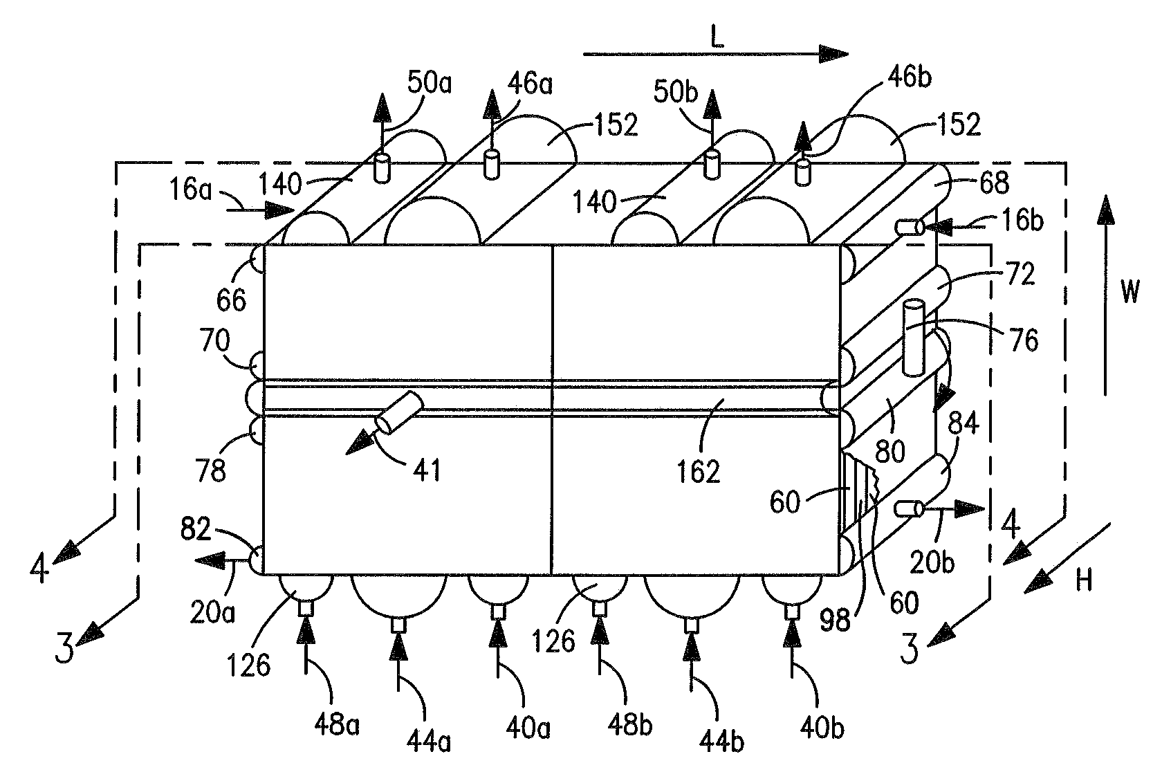
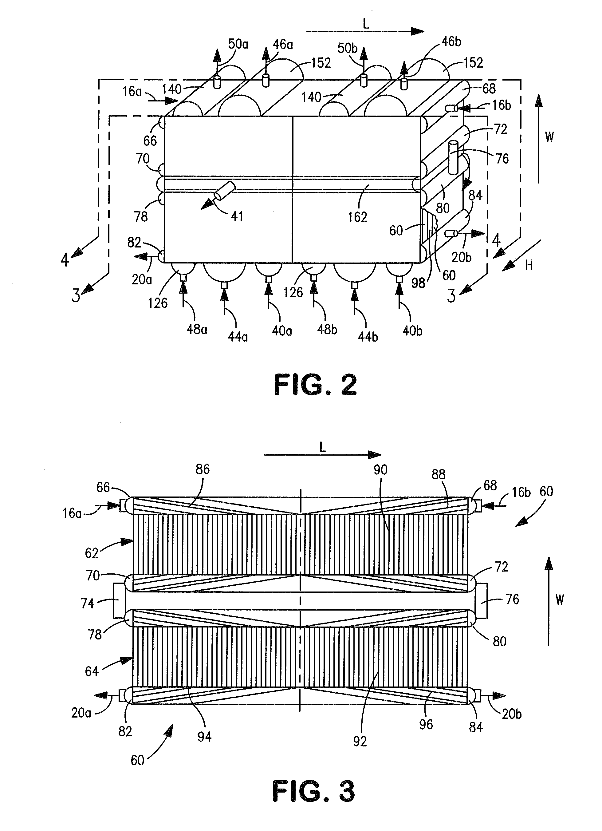
[0012]Since the second layers or possibly also the first layers are partitioned for multiple flows, there is no need to distribute the flow across the entire length dimension to prevent an excessive pressure drop from being produced by such redistribution. In this regard, the plate-fin heat exchanger of the present invention can incorporate a “series design” in which the first layer and the second layer are each divided into lengthwise sections in flow communication with one another. Each of these sections can have the width of a brazing furnace and as such heat exchangers incorporating such design can be easily scaled to accommodate a greater heat exchange duty by providing more lengthwise sections. Since the flow is fully distributed in each section, the need to redistribute flows between each section is minimized and therefore the pressure drop produced on account of such redistribution. Furthermore, since the inlets and outlets are positioned along the length dimension and flow passages are repeated within transverse sections, the total cross-sectional area for flow of each of the first fluid and each of the at least second and third fluids can be made greater than would otherwise have been obtained had the inlets and outlets been positioned at end locations of each of the lengthwise sections. This allows for less of a pressure drop within each section and the use of higher density fins with the advantage of either increasing the effective heat exchange area of each of the lengthwise section or making such lengthwise sections more compact.

Problems solved by technology

Heat exchanger efficiency is limited by the fact that each heat exchanger must be formed from individually brazed cores, which are in turn constrained in maximum cross-sectional flow area because the brazing ovens are limited in size.
Consequently, the length, width and height of any plate-fin heat exchanger is limited by the size of the furnace.
The increase in surface area inevitably comes at the expense of more frictional pressure drop.
While the degree of increase in compression that is required to overcome such increased pressure drop for the incoming air stream is not particularly severe, the amount of increased compression required for the product and waste streams is at an undesirable high level.
The problem with such redistribution points is that they each cause the flow to change direction and therefore incur a pressure drop for such reason alone.
The order of the layers in such a heat exchanger adds complexity to the design and the costs of fabrication.
Furthermore, since the flow of each layer must be distributed many times along the length, it is difficult to connect such heat exchangers in series should scale-up become necessary.
This is due to the fact that the flow must be redistributed in a downstream heat exchanger and such redistribution can lead to an unacceptable pressure drop.

Method used


Image

  • Plate-fin heat exchanger having application to air separation
  • Plate-fin heat exchanger having application to air separation
  • Plate-fin heat exchanger having application to air separation

Examples


Embodiment Construction

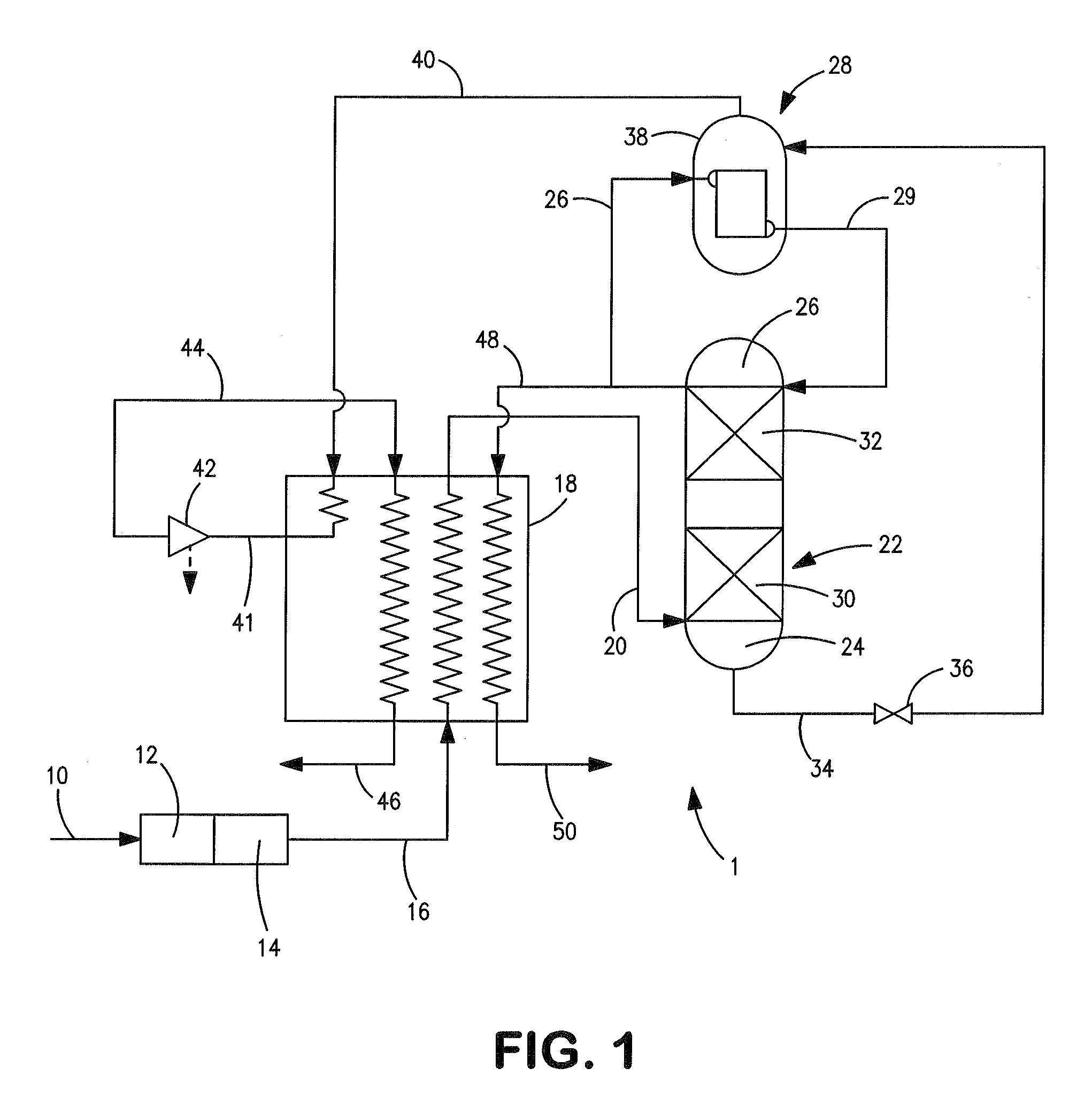
[0020]With reference to FIG. 1 an air separation plant 1 is illustrated that is used to generate nitrogen. Such an air separation plant is known as a nitrogen generator.

[0021]A feed air stream 10 is compressed at a compression unit 12 that may be a multistage compressor having inter-stage cooling between stages. The compressed and purified air stream is then introduced into a purification unit 14 that is well known in the art. Prepurification unit 14 that can be a temperature swing adsorption unit having beds of alumina or molecular sieve type adsorbent operating out of phase to remove the lower boiling components of the air such as water and carbon dioxide. The resultant compressed and purified stream 16 is cooled to at or near its dew point in main heat exchanger 18 and introduced as a compressed, purified and cooled stream 20 into a distillation column 22.

[0022]The introduction of compressed, purified and cooled air stream 20 into distillation column 22 initiates the formation of...


PUM


Abstract

A plate-fin heat exchanger having alternating layers for exchanging heat between fluids to be warmed against fluids to be cooled. One or both of the layers is subdivided into flow passages to allow for the flow of two or more fluids flowing through one of the layers to engage in indirect heat transfer with one or more fluids flowing through another adjacent layer. The flow through the heat exchanger is parallel to the width of the heat exchanger. The first and second layers provide a greater cross-sectional flow area for each of the fluids than otherwise would have been provided had the fluids flow been parallel to the length of the heat exchanger with layers thereof dedicated to the flow of each of the fluids.

Description

FIELD OF THE INVENTION[0001]The present invention relates to a plate-fin heat exchanger having application to air separation in which the warm and cold fluids to be brought into an indirect heat exchange relationship are located in alternating layers having opposed inlets and outlets along the length dimension of the heat exchanger. More particularly, the present invention relates to such a plate-fin heat exchanger in which each of the layers can be partitioned transversely into flow passages for flow of multiple fluids to be brought into an indirect heat exchange with fluids flowing in an adjacent layer.BACKGROUND OF THE INVENTION[0002]Plate-fin heat exchangers have particular application in cryogenic plants that are used in natural gas processing and in air separation. Such heat exchangers are typically fabricated from brazed aluminum heat exchanger cores that are fully brazed and welded in a vacuum brazing oven. In a typical brazing operation, fins, parting sheets and end bars ar...

Claims


Application Information

Patent Timeline
Patent Type & Authority Patents(United States)
IPC IPC(8): F28F3/00F28D7/10F25B41/00
CPCF25J3/04284F25J3/044F25J5/002F28D9/0068F28D9/0093F25J2290/32F25J2290/42F28D2021/0033F25J3/04236
Inventor JIBB, RICHARD JOHNHOWARD, HENRY EDWARD
Owner PRAXAIR TECH INC
Learn More