Turbulent flow type dynamic separation mesh disc used in range hood

A range hood and flow type technology, which is applied in the fields of oil fume removal, application, household stove, etc., can solve the problems of increasing the probability of capturing oil fume particles and increasing the pressure drop, so as to reduce the cleaning burden and avoid excessive pressure drop.

Active Publication Date: 2021-04-16
XI AN JIAOTONG UNIV
View PDF8 Cites 0 Cited by
  • Summary
  • Abstract
  • Description
  • Claims
  • Application Information

AI Technical Summary

Problems solved by technology

[0004] In the past, when the dynamic separation network disk improved the removal effect of oil fume particles, it would cause a large increase in pressure drop. In order to solve this contradictory problem, the purpose of the present invention is to provide a flow-disturbing dynamic separation network disk for the inside of the range hood. Create a small-scale complex flow area through the spoiler to increase the capture probability of oil fume particles. Since the small-scale complex flow area is not in the main flow area, a large increase in pressure drop is avoided. In addition, its processing and installation process are simple and easy to clean. According to numerical simulation The results show that the dynamic separation network disk of the present invention has a better separation effect on oil fume particles on the order of 10 μm compared with the perforated disk without spoiler baffles

Method used


Image

  • Turbulent flow type dynamic separation mesh disc used in range hood
  • Turbulent flow type dynamic separation mesh disc used in range hood
  • Turbulent flow type dynamic separation mesh disc used in range hood

Examples


Embodiment Construction

[0021] The present application will be described in further detail below through specific embodiments in conjunction with the accompanying drawings.

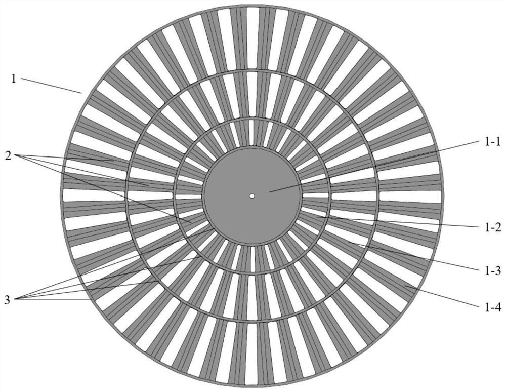
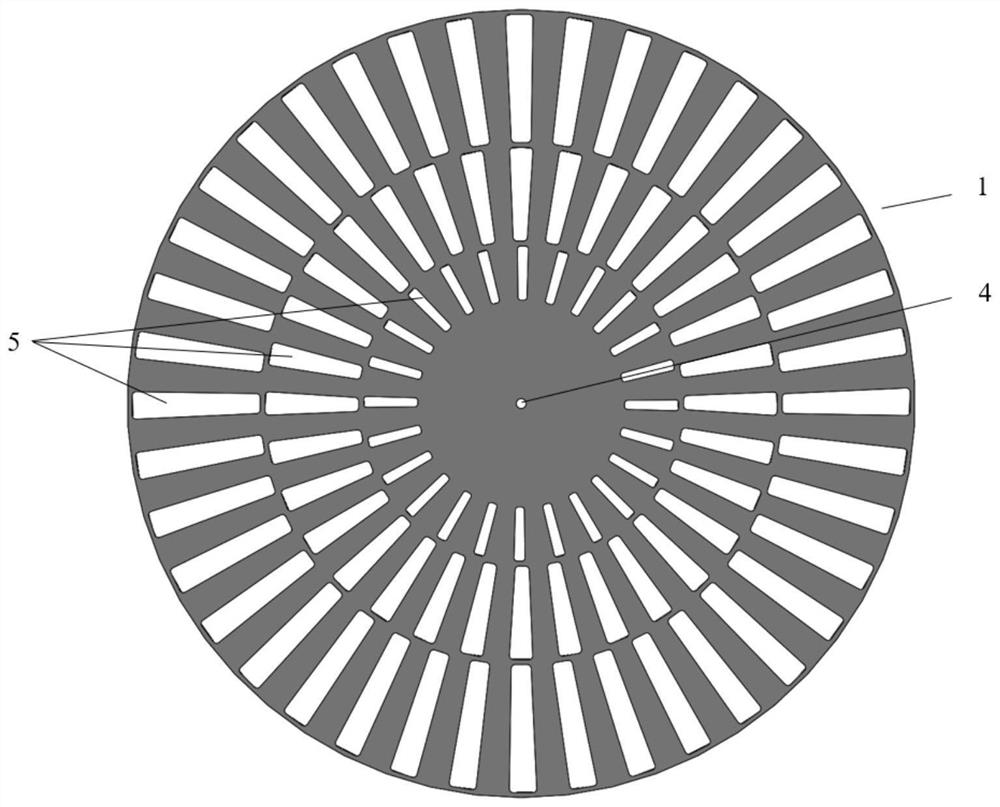
[0022] refer to figure 1 , figure 2 , a turbulence type dynamic separation network disk used in the interior of the range hood, including an integrated perforated disk 1 with a four-turn structure from the center to the periphery, and four rings of unequal-diameter baffle mounting rings are installed under the perforated disk 1 3. Spoiler baffles 2 are distributed between unequal-diameter baffle installation rings 3 .

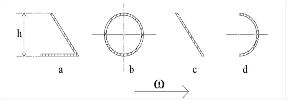
[0023] refer to image 3 , the spoiler baffle 2 is angular, spoke-shaped, oblique sheet-shaped, "C"-shaped, or other types of baffles with large changes in the pressure surface and the suction surface. Most of the soot particles directly collide with the spoiler 2 or are captured by passing through the vortex zone generated by the spoiler 2, so as to prevent the soot particles from directly contacting the per...


PUM


Abstract

The invention discloses a turbulent flow type dynamic separation mesh disc used in a range hood. The turbulent flow type dynamic separation mesh disc used in the range hood comprises an integrated perforated disc which is of a four-circle structure from the center to the periphery, and a center disc, a first-circle perforated ring, a second-circle perforated ring and a third-circle perforated ring are sequentially arranged from the center to the periphery; four circles of unequal-diameter separation blade mounting rings are mounted below the perforated disc, and turbulent flow separation blades are distributed among the unequal-diameter separation blade mounting rings; under high-speed rotation, a vortex area is formed on the suction side of the turbulent flow separation blades, except oil smoke particles directly colliding with the pressure side of the turbulent flow separation blades, most of the remaining oil smoke particles enter the vortex area and continue to keep the original motion state to be captured, the other part of the remaining oil smoke particles enter a perforated channel of the perforated disc to be captured, and all captured particles are finally collected into an oil tank to be separated. The vortex area is manufactured through the turbulent flow separation blades, oil smoke particle capturing rate is increased, and removal rate of the oil smoke particles with the order of magnitude of 10 [mu]m is greatly increased.

Description

technical field [0001] The invention relates to the technical field of high-efficiency capture of kitchen fume particles, in particular to a flow-disturbing dynamic separation network disk used inside a range hood. Background technique [0002] Kitchen fume contains a variety of toxic and harmful components, including a variety of mutagenic and carcinogenic substances, which are extremely harmful to the atmospheric environment and human health. The problem is not only a pure environmental problem, but also a social problem. [0003] At present, the oil fume separation device is usually integrated inside the range hood to ensure that the internal working fan is not easily blocked by the oil fume particles, resulting in reduced efficiency. According to the installation and operation, the oil fume separation device can be divided into static type and dynamic type. The static type is mainly based on the grille, and the dynamic type is mainly based on the rotating dynamic separa...

Claims


Application Information

Patent Timeline
Patent Type & Authority Applications(China)
IPC IPC(8): F24C15/20
Inventor 李景银陈云瑞郭朋华熊琎
Owner XI AN JIAOTONG UNIV
Why Eureka
Try Eureka