

Soldering tin melting furnace
A melting furnace and soldering technology, applied in the direction of tin feeding device, welding equipment, material removal/addition, etc., can solve problems such as dangerous operation, difficult recycling, difficulty, etc., to prevent hand burns, improve safety, and increase fault tolerance rate Effect
- Summary
- Abstract
- Description
- Claims
- Application Information
AI Technical Summary
Problems solved by technology
Method used
Image

Examples
Embodiment 1
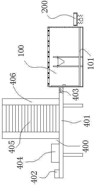
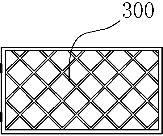
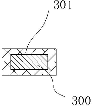
[0023] Embodiment 1, a solder melting furnace, comprising a heat-resistant cavity 100 with an opening on one side, a waste recovery tray 200 is arranged next to the heat-resistant cavity 100, and a first heating wire 101 is installed inside the heat-resistant cavity 100 One side of the opening of the heat-resistant container cavity 100 is provided with a mesh cover 300 connected by rotation. The mesh cover 300 is set on the heat-resistant container cavity 100 so that the worker's hands cannot be inserted into the heat-resistant container cavity 100, completely eliminating the possibility of the worker's hand touching the container. The possibility of solder liquid in the cavity 100 improves the safety performance. The outer side of the net cover 300 is wrapped with a first heat insulation layer 301 , the first heat insulation layer 301 can be set to reduce the temperature of the net cover 300 , and it is safer for workers to touch the net cover 300 without feeling hot.
[0024...
Embodiment 2
[0027] Embodiment 2, a solder melting furnace, comprising a heat-resistant cavity 100 with an opening on one side, a waste recovery tray 200 is arranged beside the heat-resistant cavity 100, and a first heating wire 101 is installed inside the heat-resistant cavity 100 One side of the opening of the heat-resistant container cavity 100 is provided with a mesh cover 300 connected by rotation, and the mesh cover 300 is set on the heat-resistant container cavity 100 so that the worker's hand cannot be inserted into the heat-resistant container cavity 100, completely eliminating the possibility of the worker's hand touching the container. The possibility of solder liquid in the cavity 100 improves the safety performance. The outer side of the net cover 300 is wrapped with a first heat insulation layer 301 , the first heat insulation layer 301 can be set to reduce the temperature of the net cover 300 , and it is safer for workers to touch the net cover 300 without feeling hot.
[00...
Embodiment 3
[0031] Embodiment 3, a solder melting furnace, comprising a heat-resistant cavity 100 with an opening on one side, a waste recovery tray 200 is arranged next to the heat-resistant cavity 100, and a first heating wire 101 is installed inside the heat-resistant cavity 100 One side of the opening of the heat-resistant container cavity 100 is provided with a mesh cover 300 connected by rotation. The mesh cover 300 is set on the heat-resistant container cavity 100 so that the worker's hands cannot be inserted into the heat-resistant container cavity 100, completely eliminating the possibility of the worker's hand touching the container. The possibility of solder liquid in the cavity 100 improves the safety performance. The outer side of the net cover 300 is wrapped with a first heat insulation layer 301 , the first heat insulation layer 301 can be set to reduce the temperature of the net cover 300 , and it is safer for workers to touch the net cover 300 without feeling hot.
[0032...
PUM
 Abstract
Description
Claims
Application Information