
Soldering tin melting furnace

A melting furnace and soldering technology, which is applied in the direction of tin feeding device, welding equipment, metal processing equipment, etc., can solve the problems of dangerous operation, difficult recycling, difficulty, etc., and achieve the effect of preventing hand burns, improving safety, and increasing fault tolerance rate

Active Publication Date: 2015-05-27
NINGBO HENGSHENG ELECTRIC
View PDF6 Cites 0 Cited by
  • Summary
  • Abstract
  • Description
  • Claims
  • Application Information

AI Technical Summary

Problems solved by technology

When workers use this kind of solder melting furnace, they first put in tin bars to melt the solder, then organize a small bundle of wires by hand, dip the head of the small bundle of wires into the solder liquid to dip in the solder, and then pull it out. If the dipped solder is too much, part of it will be thrown away in the waste recycling tray, and the small bundles of wires will be fixed together after the solder solidifies. However, there are many dangers and operational difficulties in this structure and production method: 1. Workers need to dip their hands into a hot solder melting furnace to get the solder liquid, and the solder melting furnace does not have any protective measures. Personal injury caused by contact with solder liquid
[0004] 2. There is no scale mark in the solder melting furnace, and the height of the solder liquid level is difficult to control. When workers dip in the solder liquid, if the solder liquid level is too low, the fixing strength of the wire may not be enough. If the solder liquid level is too high, the wire After the wire is inserted into the liquid surface, the plastic shell will touch the solder liquid, making the plastic shell melt in the solder liquid
[0005] 3. When workers shake off excess solder in the waste recycling tray, since the solder is not completely solidified at this time, it will stick to the waste recycling tray. It is very difficult to remove it from the waste recycling tray after the solder is completely cooled and solidified.

Method used


Image

  • Soldering tin melting furnace
  • Soldering tin melting furnace
  • Soldering tin melting furnace

Examples


Embodiment 1

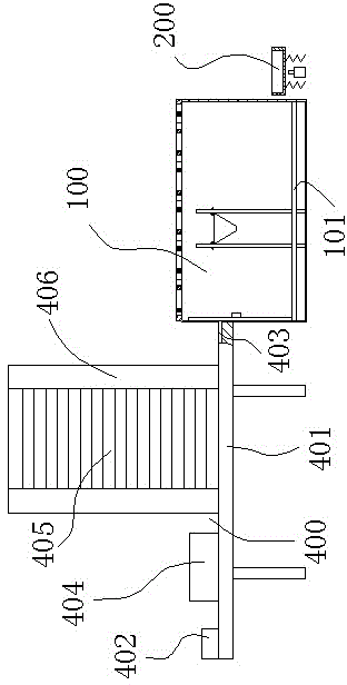
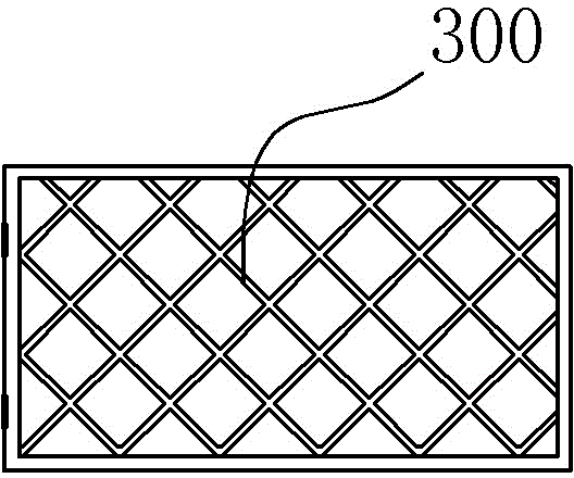
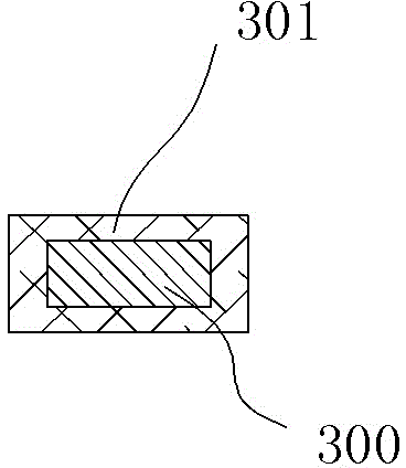
[0023] Embodiment 1, a solder melting furnace, comprising a heat-resistant cavity 100 with an opening on one side, a waste recovery tray 200 is arranged next to the heat-resistant cavity 100, and a first heating wire 101 is installed inside the heat-resistant cavity 100 One side of the opening of the heat-resistant container cavity 100 is provided with a mesh cover 300 connected by rotation. The mesh cover 300 is set on the heat-resistant container cavity 100 so that the worker's hands cannot be inserted into the heat-resistant container cavity 100, completely eliminating the possibility of the worker's hand touching the container. The possibility of solder liquid in the cavity 100 improves the safety performance. The outer side of the net cover 300 is wrapped with a first heat insulation layer 301 , the first heat insulation layer 301 can be set to reduce the temperature of the net cover 300 , and it is safer for workers to touch the net cover 300 without feeling hot.

[0024...

Embodiment 2

[0027] Embodiment 2, a solder melting furnace, comprising a heat-resistant cavity 100 with an opening on one side, a waste recovery tray 200 is arranged beside the heat-resistant cavity 100, and a first heating wire 101 is installed inside the heat-resistant cavity 100 One side of the opening of the heat-resistant container cavity 100 is provided with a mesh cover 300 connected by rotation. The mesh cover 300 is set on the heat-resistant container cavity 100 so that the worker's hands cannot be inserted into the heat-resistant container cavity 100, completely eliminating the possibility of the worker's hand touching the container. The possibility of solder liquid in the cavity 100 improves the safety performance. The outer side of the net cover 300 is wrapped with a first heat insulation layer 301 , the first heat insulation layer 301 can be set to reduce the temperature of the net cover 300 , and it is safer for workers to touch the net cover 300 without feeling hot.

[0028]...

Embodiment 3

[0031] Embodiment 3, a solder melting furnace, comprising a heat-resistant cavity 100 with an opening on one side, a waste recovery tray 200 is arranged next to the heat-resistant cavity 100, and a first heating wire 101 is installed inside the heat-resistant cavity 100 One side of the opening of the heat-resistant container cavity 100 is provided with a mesh cover 300 connected by rotation. The mesh cover 300 is set on the heat-resistant container cavity 100 so that the worker's hands cannot be inserted into the heat-resistant container cavity 100, completely eliminating the possibility of the worker's hand touching the container. The possibility of solder liquid in the cavity 100 improves the safety performance. The outer side of the net cover 300 is wrapped with a first heat insulation layer 301 , the first heat insulation layer 301 can be set to reduce the temperature of the net cover 300 , and it is safer for workers to touch the net cover 300 without feeling hot.

[0032...


PUM


Abstract

The invention discloses a soldering tin melting furnace which comprises a heat-resisting cavity, wherein a first heating wire is arranged inside the heat-resisting cavity, a waste-material-recycling disc is arranged beside the heat-resisting cavity, a heat-resisting support is further arranged in the heat-resisting cavity and is provided with a big-end-up cone-shaped shell, and a second through hole is arranged at the bottom of the cone-shaped shell. The soldering tin melting furnace can prevent plastic coated outside wires from penetrating through the second through hole and effectively prevent the plastic from being melted in soldering tin liquid, improves error-tolerant rates in work and ensures that workers feel relaxed to work, and due to the fact that the cone-shaped shell is arranged, safety can be effectively improved, and hands of the workers can be prevented from being scalded.

Description

technical field [0001] The invention relates to a solder melting furnace, which is used for melting and coating the solder on the outside of exposed wires, and fixing and bundling the wires after the solder condenses. Background technique [0002] Solder melting furnace is a furnace used to melt solder bars. It is used to dip a small amount of solder liquid on the head of a bundle of exposed wires. After the solder is cooled and solidified, the wires are fixed and bundled. It is often used in power distribution. Fixing of wires in box production. [0003] Existing solder melting furnaces generally include a heat-resistant cavity, in which a plurality of first heating wires for melting solder and a waste recovery tray for throwing away excess solder are arranged. When workers use this kind of solder melting furnace, they first put in tin bars to melt the solder, then organize a small bundle of wires by hand, dip the head of the small bundle of wires into the solder liquid to...

Claims


Application Information

Patent Timeline
Patent Type & Authority Patents(China)
IPC IPC(8): B23K3/06
CPCY02P70/10
Inventor 周荣武周军安
Owner NINGBO HENGSHENG ELECTRIC
Learn More