Mold insert motion structure

A technology of motion structure and inserts, which is applied in the field of motion structure of mold inserts, can solve problems such as unstable exhaust, high cost, and poor exhaust, and achieve the effects of reducing adverse phenomena, facilitating molding, and reliable operation

Inactive Publication Date: 2013-05-29
KENTA ELECTRONIC MFG KUNSHAN CO LTD
View PDF3 Cites 1 Cited by
  • Summary
  • Abstract
  • Description
  • Claims
  • Application Information

AI Technical Summary

Problems solved by technology

Its main function is to facilitate the disassembly of the mold and to repair the mold in a very short time after the mold is damaged. For some products, if the ordinary mold structure is used, the product defect rate will be high. For example, the bakelite products are small. The friction force is high, and the damage to the inner cavity of the mold is faster. Under normal circumstances, the original ejector pin cannot be fully exhausted, and the smaller flat ejector is easily damaged, and the exhaust is unstable and the cost is high.
As a result, it is impossible to find out the defects of the product in time, and the waste of labor increases the cost. After the insert is inserted into this type of mold, the insert is easily damaged, and it is easy to block the mold, resulting in poor exhaust

Method used


Image

  • Mold insert motion structure
  • Mold insert motion structure
  • Mold insert motion structure

Examples


Embodiment Construction

[0011] In order to deepen the understanding of the present invention, the present invention will be further described below in conjunction with the embodiments and accompanying drawings. The embodiments are only used to explain the present invention and do not constitute a limitation to the protection scope of the present invention.

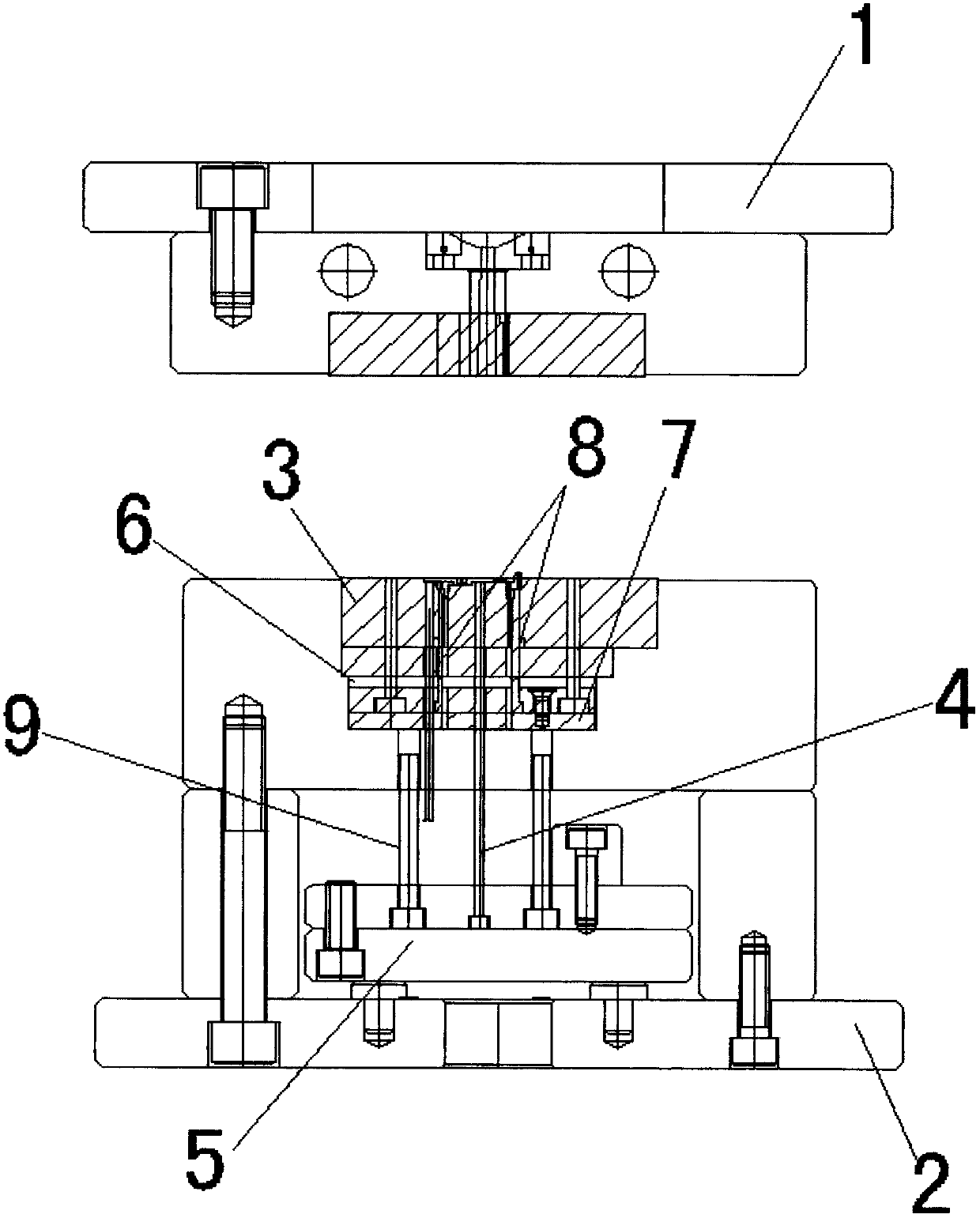
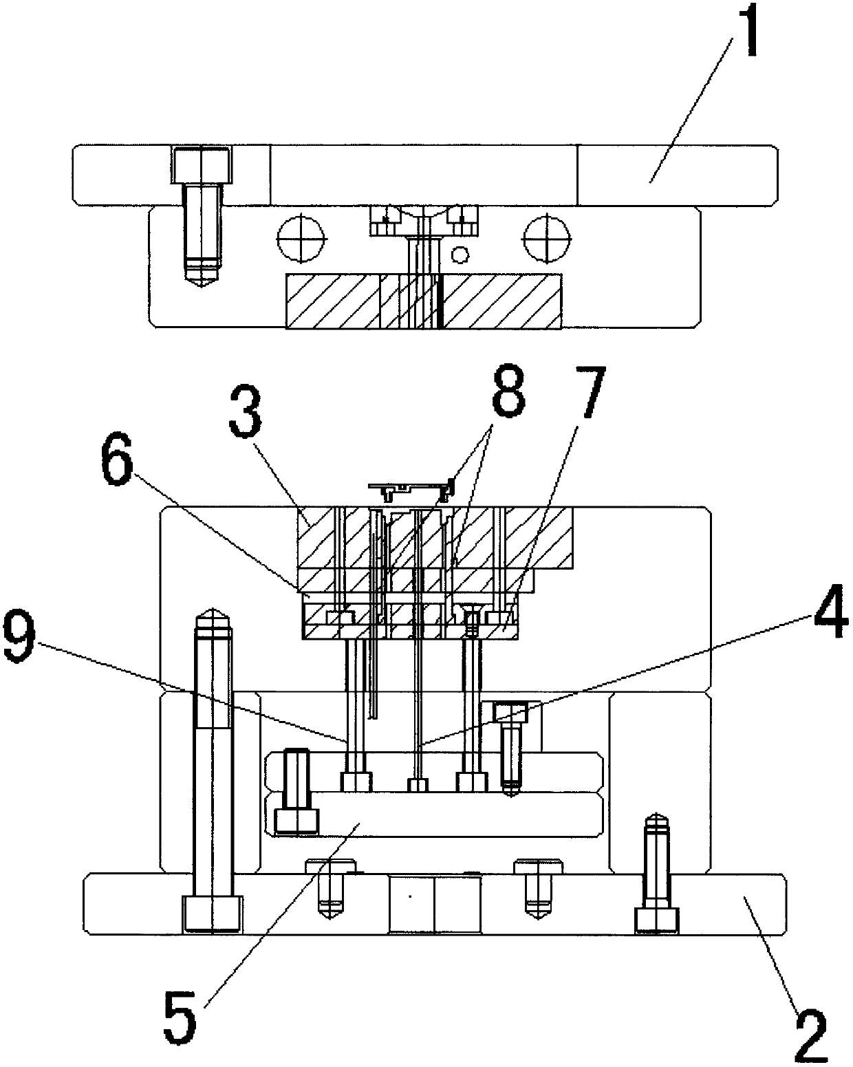
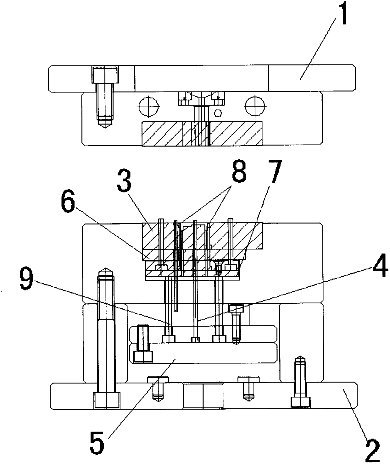
[0012] figure 1 An embodiment of the movement structure of a mold insert of the present invention is shown, including an upper mold 1, a lower mold 2, a mold core 3 and a core ejection mechanism, and the ejection mechanism includes an ejector pin 4 and an ejector pin plate 5, The lower end of the mold core 3 is provided with a cavity 6, a slider 7 vertically sliding up and down is arranged in the cavity 6, and a plurality of inserts 8 are arranged on the side of the mold cavity of the mold core 3, the inserts 8 The lower end is fixed on the slide block 7, and a plurality of ejector pins 9 are also arranged on the ejector pin plate 4, a gap is pro...


PUM


Abstract

The invention discloses a mold insert motion structure which comprises an upper mold, a lower mold, a mold core and a mold core ejection mechanism; the ejection mechanism comprises an ejection needle and an ejection needle plate; the lower end of the mold core is provided with an empty cavity; the empty cavity is internally provided with a slide block vertically sliding up and down; the side edge of a mold cavity of the mold core is provided with a plurality of inserts; the lower ends of the inserts are fixed on the slide block; the ejection needle plate is also provided with a plurality of ejection rods; a clearance is formed between the upper end of each ejection rod and the slide block; and the lower ends of the ejection rods are fixed in the ejection needle plate. The general inserts are combined with the ejection rods so as to form a novel insert motion mechanism, and a novel mode for solving air trapping is formed, and the appearance requirement of the product surface can be ensured, and the product reject ratio also can be lowered. In the prior art, the ejection needle or a flat ejector is used for exhausting air, compared with the existing ejection needle air exhaust structure, the mold insert motion structure can be used for enabling the inserts not to be difficult to damage; and the mold insert motion structure can exhaust the air fully, runs reliably, is low in cost, is convenient to form, and reduces the unhealthy phenomena in forming.

Description

technical field [0001] The invention relates to a mould, in particular to an insert moving structure of the mould. Background technique [0002] The insert acts as a removable iron block in the mold. Its main function is to facilitate the disassembly of the mold and to repair the mold in a very short time after the mold is damaged. For some products, if the ordinary mold structure is used, the product defect rate will be high. For example, the bakelite products are small. The friction force is high, and the damage to the inner cavity of the mold is faster. Under normal circumstances, the original ejector pin cannot be fully exhausted, and the smaller flat ejector is easily damaged, and the exhaust is unstable and the cost is high. As a result, it is impossible to find out the defects of the product in time, and the waste of labor increases the cost. After the insert is inserted into this type of mold, the insert is easily damaged, and it is easy to block the mold, resulting...

Claims


Application Information

Patent Timeline
Patent Type & Authority Applications(China)
IPC IPC(8): B29C45/34B29C45/33
Inventor 蔡峻峰
Owner KENTA ELECTRONIC MFG KUNSHAN CO LTD
Why Eureka
Try Eureka