Configuration of vehicle heat exchanger

A heat exchanger, outdoor heat exchanger technology, applied in vehicle energy storage, vehicle components, electric vehicles, etc., can solve problems such as capacity decline and insufficient heating capacity

Inactive Publication Date: 2013-05-29
DENSO CORP
View PDF7 Cites 35 Cited by
  • Summary
  • Abstract
  • Description
  • Claims
  • Application Information

AI Technical Summary

Problems solved by technology

If a heat pump system is adopted with the arrangement structure of the vehicle heat exchanger as described above, the heating capa

Method used


Image

  • Configuration of vehicle heat exchanger
  • Configuration of vehicle heat exchanger
  • Configuration of vehicle heat exchanger

Examples


Embodiment Construction

[0014] The present invention will be described below with reference to the drawings, and can be understood more clearly in consideration of the description of the embodiments of the present invention. Hereinafter, an embodiment of the present invention will be described with reference to the drawings. In each embodiment, the same code|symbol is attached|subjected to the part of the same structure, and the description is abbreviate|omitted.

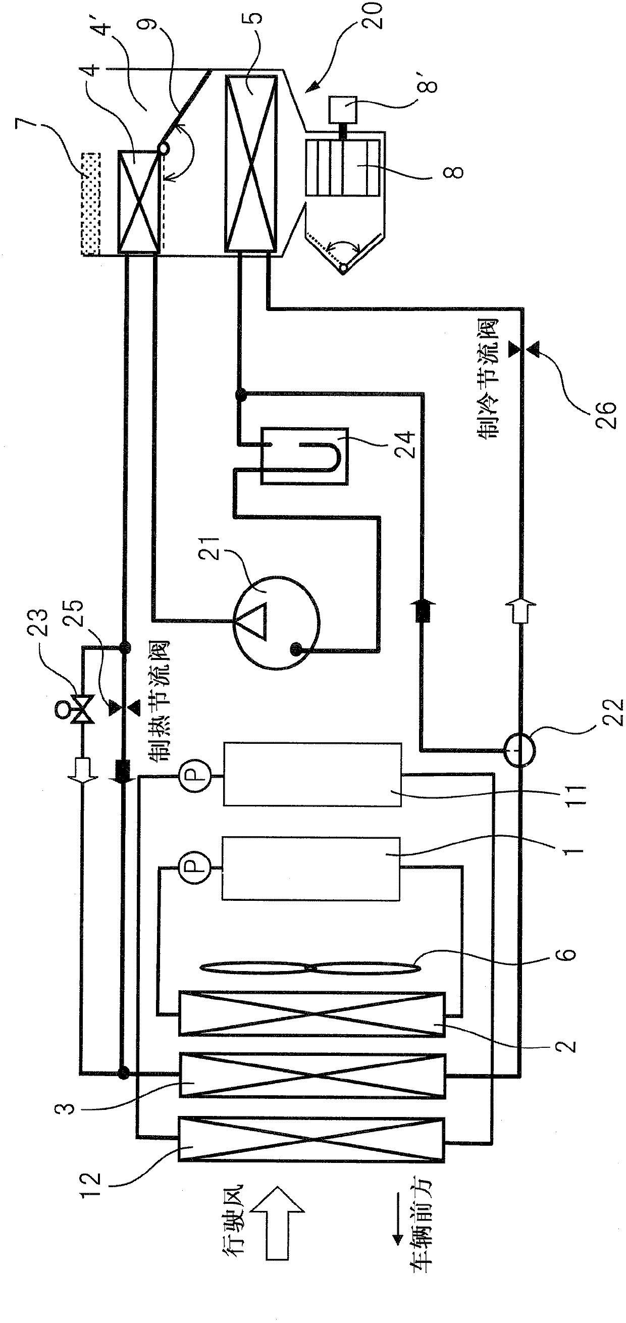
[0015] figure 2 It is an explanatory drawing explaining one embodiment of this invention as an example. This embodiment is an example of an overall system applied to a hybrid vehicle (HEV, PHEV). In the case of electric vehicles (EV), fuel cell vehicles, etc., there is no figure 2 High water temperature radiator 2. An embodiment of the invention is not necessarily limited to figure 2 It can also be applied to other heat pump type air conditioners.

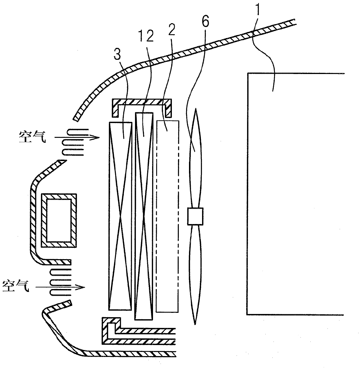
[0016] 20 is an indoor unit unit (HVAC) of an air conditioner, and an indoor blowe...


PUM


Abstract

The present invention provides a configuration of a vehicle heat exchanger. The configuration of the vehicle heat exchanger comprises an outdoor heat exchanger of a heat pump system of a vehicle air conditioning device and a low water temperature radiator used for cooling the low temperature heating elements, including a vehicle driving motor, and is characterized in that relative to the outdoor heat exchanger, the low water temperature radiator is arranged at the upstream side of a cooling airflow direction.

Description

technical field [0001] The present invention relates to a condenser (hereinafter referred to as an outdoor heat exchanger) for a heat pump system of an air conditioner in a hybrid electric vehicle (HEV), an electric vehicle (EV), a plug-in hybrid electric vehicle (PHEV), etc. , an arrangement structure of a vehicle heat exchanger in which a low-temperature radiator for cooling electronic equipment such as an inverter is arranged on the upstream side of the cooling air flow direction. Background technique [0002] As shown in Japanese Patent Application Laid-Open No. 2011-98628, a hybrid vehicle (HEV, PHEV) is provided with two drive sources, an engine and a running motor, and is equipped with a device for converting DC power from an onboard secondary battery into AC power. It is also an inverter that supplies the driving motor. In such a hybrid vehicle, in addition to the cooling of the engine, the running motor and the inverter of the hybrid system also need to be cooled. ...

Claims


Application Information

Patent Timeline
IPC IPC(8): B60H1/22
CPCY02T10/7241Y02T10/7077
Inventor 铃木敏且
Owner DENSO CORP
Why Eureka
Try Eureka