
High-efficient powder selecting machine

A kind of powder separator, high-efficiency technology, applied in agricultural machinery equipment, solid separation, separating solids from solids with air flow, etc., can solve the problem that the stator angle of the powder separator cannot be adjusted, which is unfavorable for energy saving and consumption reduction, and cannot form classification force field etc.

Inactive Publication Date: 2013-06-05
洛阳宇航重工科技股份有限公司
View PDF5 Cites 4 Cited by
  • Summary
  • Abstract
  • Description
  • Claims
  • Application Information

AI Technical Summary

Problems solved by technology

[0004] The inventor found in the process of realizing the present invention that: the stator angle of the current powder separator is usually not adjustable, so that the powder separator cannot be well adapted to the screening of materials with different particle sizes, which affects the efficiency of the powder separator; The plate structure setting of the blade makes the front and rear widths of the flow section inconsistent, and the resistance of the powder separator body increases, resulting in a larger system fan, which is not conducive to energy saving and consumption reduction; in addition, the powder separator is usually designed based on the principle of centrifugal classification force field, but , due to the wide variety of rotor shapes and the unreasonable width and height of the classification area, it is impossible to form a stable pressure difference and a stable air velocity in the classification area, so that a stable classification force field cannot be formed, which affects the efficiency of the powder classifier

Method used


Image

  • High-efficient powder selecting machine
  • High-efficient powder selecting machine
  • High-efficient powder selecting machine

Examples


Embodiment Construction

[0023] In order to further explain the technical means and effects that the present invention takes to achieve the intended purpose of the invention, below in conjunction with the accompanying drawings and preferred embodiments, its specific implementation, structure, features and effects of the high-efficiency powder separator proposed according to the present invention , as detailed below.

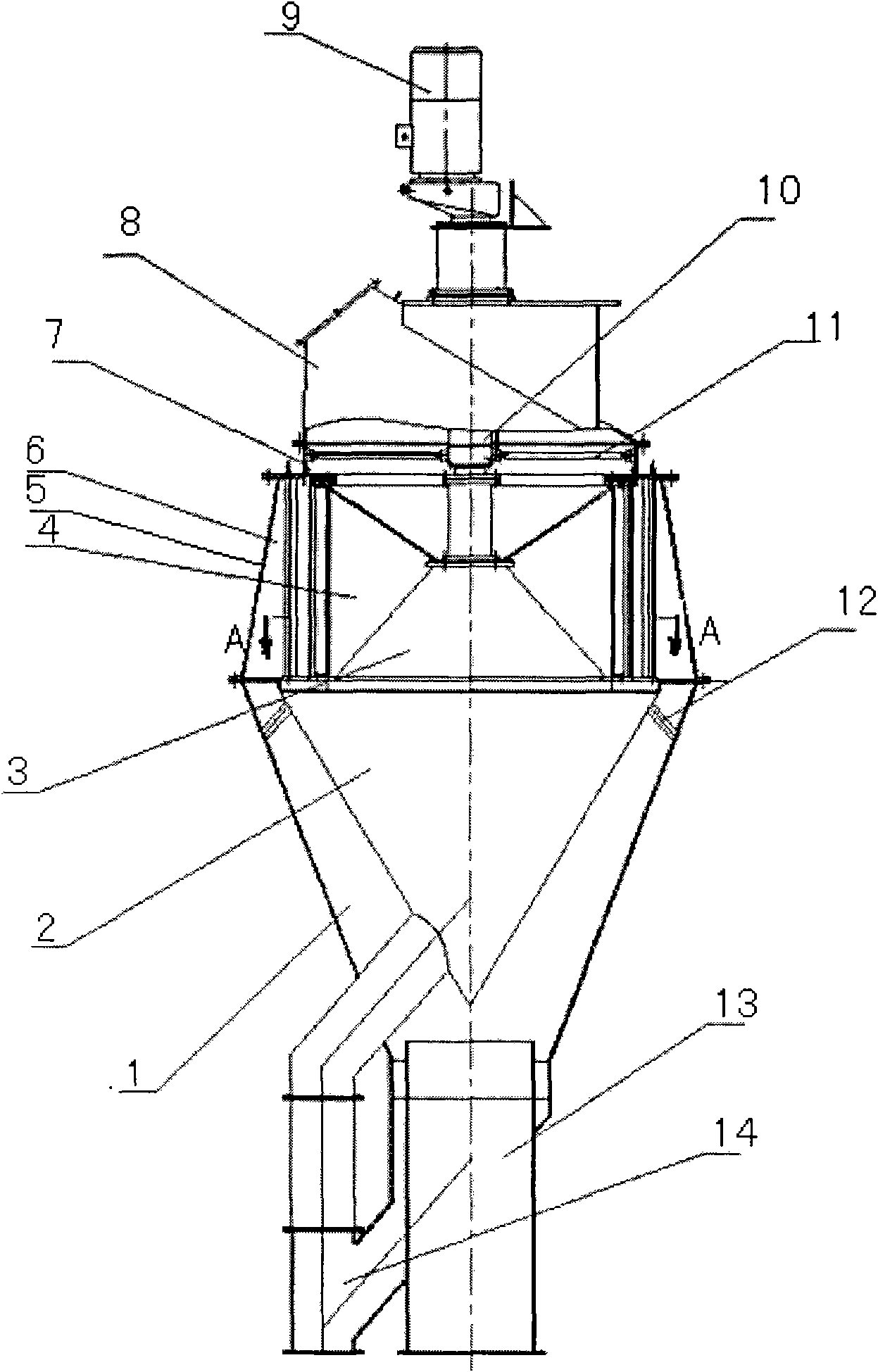
[0024] figure 1 The high-efficiency powder separator shown mainly includes two parts: the inside of the machine body and the outside of the machine body. The inside of the machine body is provided with a main shaft 10, a stator 6, a rotor 4, a lower rotor cone 3 and a coarse material collection cone 2. The outside of the body is provided with a transmission part 9, an upper cover body 8, a frame 7, a middle cover body 5 and a lower cover body 1 from top to bottom.

[0025] The upper cover body 8 is a hollow truncated conical structure with an upper part and a lower circle, and the lower...


PUM


Abstract

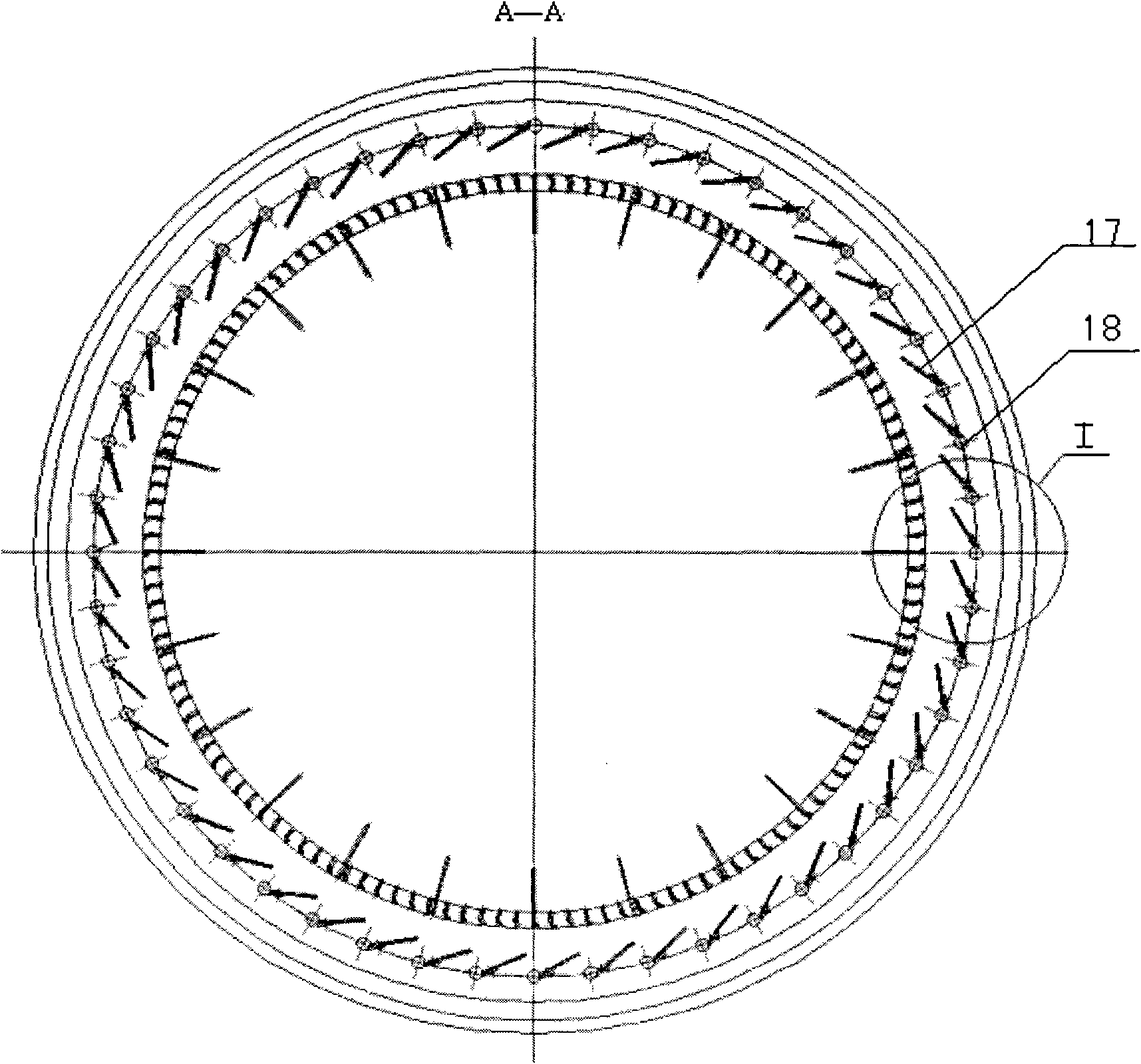
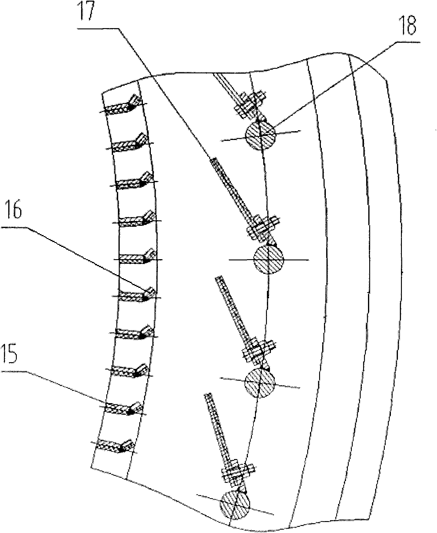
The invention relates to a high-efficient powder selecting machine which mainly comprises that a lower cover body is connected with a middle cover body, the middle cover body is connected with an upper cover body, and the upper cover body is connected with an upper end of a main shaft, a coarse grain material collection cone is connected with a stator lower end and the lower portion of the lower cover body. A rotor lower cone ring is connected with a lower end of the main shaft and a rotor connecting rod. Stators are arranged on the periphery of a rotor along the peripheral direction, the upper ends of the stators are connected with a frame through flanges, and the rotor is in a cage-shaped structure formed by vertical rotor blades arranged along the periphery direction and a horizontal partition plate. Each stator comprises a stator blade and a stator shaft, the stator blades are arranged on the stator shafts along the tangential direction of the stator shafts, and the upper ends of the stator shafts extend out of the frame. A transmission part drives the main shaft, and the lower end the main shaft is connected with the frame through a main shaft pull rod in the circumferential direction. Through the technical scheme, the efficiency of the high-efficient powder selecting machine is improved, and energy saving and consumption reduction are achieved.

Description

technical field [0001] The invention relates to a material screening technology, in particular to a high-efficiency powder separator matched with a pulverizer to process electrolyte crust blocks. Background technique [0002] The finished material of the pulverizer is obtained through the sorting of the classifier. How to make the classifier perform efficient material classification is very important for material screening technology. [0003] The key to the design of the powder separator is the structural design of the rotor and stator. The existing guide blades of the stator part are usually of flat plate structure, and need to have a radial angle relative to the center line of the powder classifier. It can be adjusted according to the change of the airflow speed and must be determined through a test run with material [0004] The inventor found in the process of realizing the present invention that: the stator angle of the current powder separator is usually not adjusta...

Claims


Application Information

Patent Timeline
IPC IPC(8): B02C23/18B07B7/00B07B7/01B07B7/083
CPCY02P60/15
Inventor 岳新立赵永翔李晓雷张岩高洁
Owner 洛阳宇航重工科技股份有限公司
Learn More