
Powder separating machine for cement raw material, clinker and slag vertical type roller mill

A technology of cement raw materials and vertical roller mill, which is applied in the direction of separating solids from solids with airflow, solid separation, chemical instruments and methods, etc. It can solve the unreasonable width and height of the classification area and affect the stable operation of the system for a long time , unable to form a stable graded force field and other problems, to achieve the effect of compact structure, high cost performance, and convenient manufacturing and installation

Inactive Publication Date: 2012-01-25
CITIC HEAVY INDUSTRIES CO LTD +1
View PDF4 Cites 0 Cited by
  • Summary
  • Abstract
  • Description
  • Claims
  • Application Information

AI Technical Summary

Problems solved by technology

[0003] Looking at the main structural parameters of powder classifiers in the past, first of all, the guide vane of the stator part needs to have a radial angle with respect to the center line of the powder classifier. The composition of the material and the airflow speed change, which must be determined through a test run with the material. However, most of the current roller vertical mill separators have a non-adjustable stator angle, which affects the long-term stable operation of the system; secondly, the current powder separator The plate structure of the guide vane of the machine makes the front and rear widths of the flow section inconsistent, and the resistance of the powder concentrator body increases, resulting in a larger system fan, which is not conducive to the macro goal of energy saving and consumption reduction; Grading force field, but the shape of the rotor varies greatly, the width and height of the grading area are unreasonable, etc., can not form a stable pressure difference and a stable air velocity in the grading area, so it is also impossible to form a stable grading force field, so that it cannot become a The real high-efficiency powder separator

Method used


Image

  • Powder separating machine for cement raw material, clinker and slag vertical type roller mill
  • Powder separating machine for cement raw material, clinker and slag vertical type roller mill
  • Powder separating machine for cement raw material, clinker and slag vertical type roller mill

Examples


Embodiment Construction

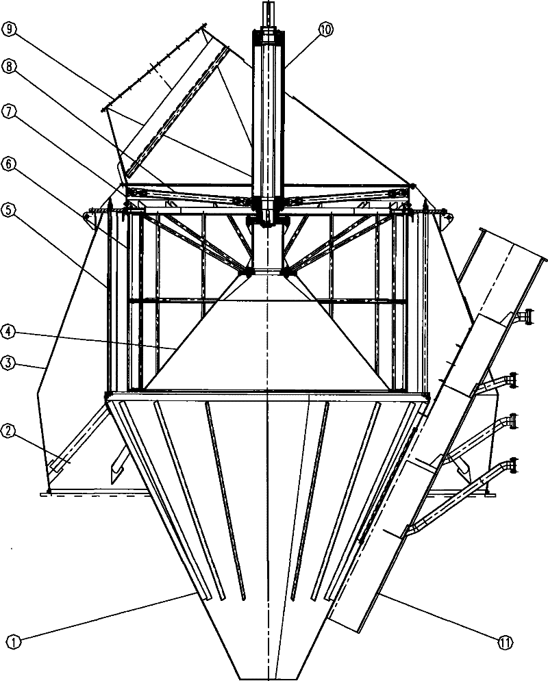
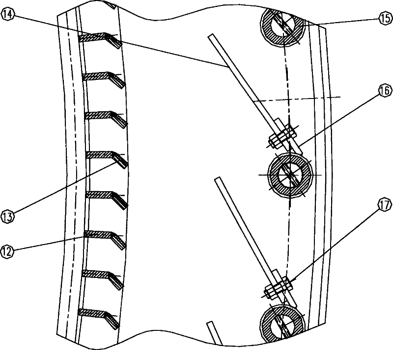
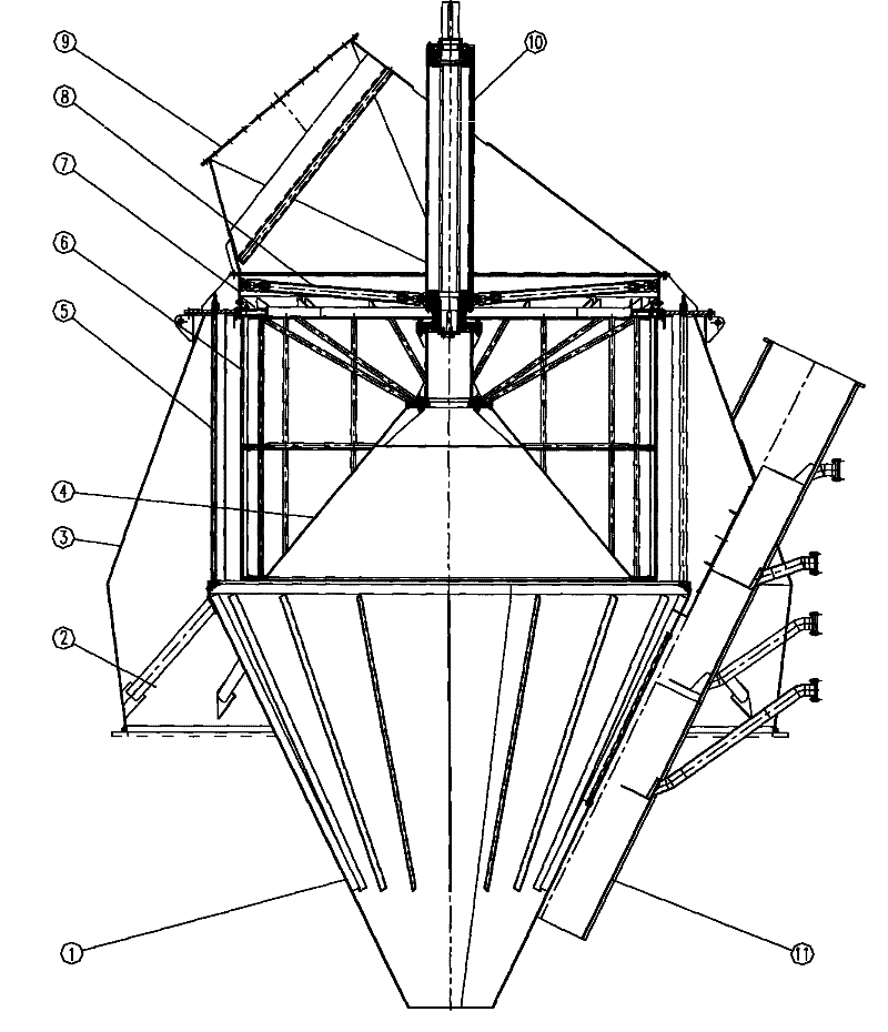
[0018] pass figure 1 , 2 It can be seen that: the separator for cement raw material, clinker and slag vertical roller mill of the present invention, its main structure is composed of an external upper casing 9, a middle casing 7, a lower casing 3 and a feed chute 11 and the internal main shaft 10, main shaft outer tube strut 8, rotor 6, rotor lower cone 4, and coarse material collection cone 1; wherein the upper shell 9 is a hollow truncated cone structure with upper and lower circles, and the upper shell 9 Bolt connection between the lower flange and the upper flange of the middle shell 7; the middle shell 7 is hollow cylindrical, the bolt connection between the lower flange of the middle shell 7 and the upper flange of the lower shell 3; It is a hollow frustum-shaped structure with thin ends and thick middle; the center line of the feed chute 11 forms a certain angle with the longitudinal center line of the powder separator, and the feed chute 11 is located outside the low...


PUM


Abstract

The invention provides a powder concentrator of a vertical roller mill used for cement material, clinkers and slags. The main structure of the body of the powder concentrator consists of an upper part housing (9), a middle part housing (7), a lower part housing (3) and a feed downspouting (11) at the outside as well as a main shaft (10), a supporting rod 8 of the outer cylinder of the main shaft, a rotor (6), a lower prick ring (4) of the rotor and a thick grain material collecting prick (1) at the inside. The powder concentrator has the advantages of good dispersing effect, high grading rate and grading precision, wide grading granularity range, small device resistance, being easy to realize maximazation, compact structure, small machine body size, convenient manufacture and mounting, stable operation, small vane abrasion and high performance price ratio.

Description

technical field [0001] The invention belongs to the technical field of mining machinery, and in particular relates to a powder separator for vertical roller mills for cement raw materials, clinker and slag. Background technique [0002] The finished material of the vertical roller mill is obtained through the classification of the classifier, so it is necessary to study what type of classifier can be used to produce the most effective classification effect. [0003] Looking at the main structural parameters of powder classifiers in the past, first of all, the guide vane of the stator part needs to have a radial angle with respect to the center line of the powder classifier. The composition of the material and the airflow speed change, which must be determined through a test run with the material. However, most of the current roller vertical mill separators have a non-adjustable stator angle, which affects the long-term stable operation of the system; secondly, the current po...

Claims


Application Information

Patent Timeline
Patent Type & Authority Patents(China)
IPC IPC(8): B07B7/00B07B7/01B07B7/083
Inventor 张廷龙张路明黄敏马颖吴晓红
Owner CITIC HEAVY INDUSTRIES CO LTD
Learn More