A kind of processing method of injection molding surface gear electrode and injection molding surface gear
A processing method and technology of face gears, applied in electric processing equipment, electrode manufacturing, components with teeth, etc., can solve the problems of low precision of face gears, expensive equipment, complicated process, etc., and achieve low transmission noise and low cost , the effect of accurate data
- Summary
- Abstract
- Description
- Claims
- Application Information
AI Technical Summary
Problems solved by technology
Method used
Image
Examples
Embodiment 1
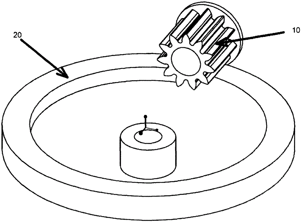
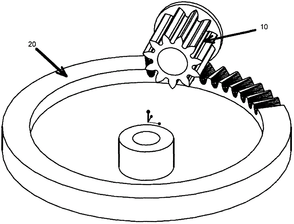
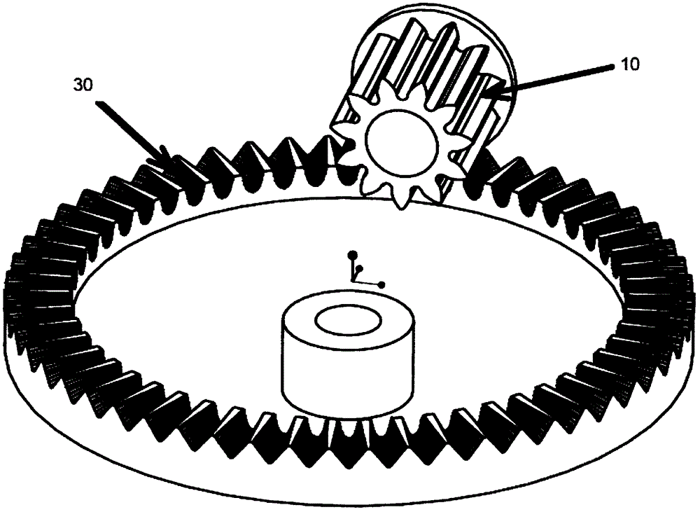
[0037] This embodiment provides a method for processing an injection-molded surface gear electrode. The surface gear referred to in the present invention means that all the gear teeth are on the same disc surface. In fact, when we process an injection-molded surface gear electrode, we know that the surface The outer diameter of the gear, the inner diameter of the face gear, but the tooth shape data of the face gear is unknown, so the tooth shape data of the face gear we want to generate. At the same time, before processing the required face gear, we know the relative position of the face gear and the cylindrical gear driven by the face gear, and the cross-sectional diameter of the cylindrical gear driven by the face gear, the number of teeth of the cylindrical gear, and the We can also know the data of tooth pitch and tooth depth of cylindrical gear. So, if Figure 1-3 As shown, the processing method of the injection surface gear electrode is as follows:
[0038] S1. Constru...
Embodiment 2
[0044] The difference between this embodiment and Embodiment 1 is that the teeth of the face gear are not on the same disc surface, the face gear is actually a bevel gear, the rotation center axis of the bevel gear and the center The included angle of the shaft is less than 90°, the processing method of the gear electrode on the injection surface is the same as the other steps in Example 1, the difference is:
[0045] S2. In the UG software, a conical wheel blank is constructed according to the inner diameter of the actual face gear tooth disc, the outer diameter of the face gear tooth disc, and the central axis of the face gear and the angle with the central axis of the cylindrical gear driven by the face gear. For example: build a bevel gear with an inner diameter of 10cm and an outer diameter of 11cm, the central axis of the face gear and the central axis of the cylindrical gear driven by the face gear at an angle of 60°.
Embodiment 3
[0047] The processing steps of this embodiment are the same as those of Embodiment 1. The difference is that the tooth depth of the face gear is different from that of the cylindrical gear. The tooth depth of the cylindrical gear is 1.5 cm, while the tooth depth of the face gear is 1 cm. Therefore Set the distance between the central axis of the cylindrical gear and the disc surface of the face gear to be 4cm, then the distance between the central axis of the cylindrical gear and the disc surface of the face gear will be larger than that in Example 1, so adjust the relative positions of the cylindrical gear and the face gear Different face gear tooth depths can be generated. When the face gear and the spur gear are driving, the teeth of the face gear are not completely inserted into the tooth grooves of the spur gear, while the teeth of the spur gear are completely inserted into the tooth grooves of the face gear.
PUM
| Property | Measurement | Unit |
|---|---|---|
| angle | aaaaa | aaaaa |
Abstract
Description
Claims
Application Information
 - R&D
- Intellectual Property
- Life Sciences
- Materials
- Tech Scout
- Unparalleled Data Quality
- Higher Quality Content
- 60% Fewer Hallucinations
Browse by: Latest US Patents, China's latest patents, Technical Efficacy Thesaurus, Application Domain, Technology Topic, Popular Technical Reports.
© 2025 PatSnap. All rights reserved.Legal|Privacy policy|Modern Slavery Act Transparency Statement|Sitemap|About US| Contact US: help@patsnap.com


