

Method for manufacturing an idler assembly
An idler and wheel blank technology, applied in the field of shifting clutch devices, can solve the problem of unreachable tooth precision and achieve high-strength effects
- Summary
- Abstract
- Description
- Claims
- Application Information
AI Technical Summary
Problems solved by technology
Method used
Image

Examples
Embodiment Construction
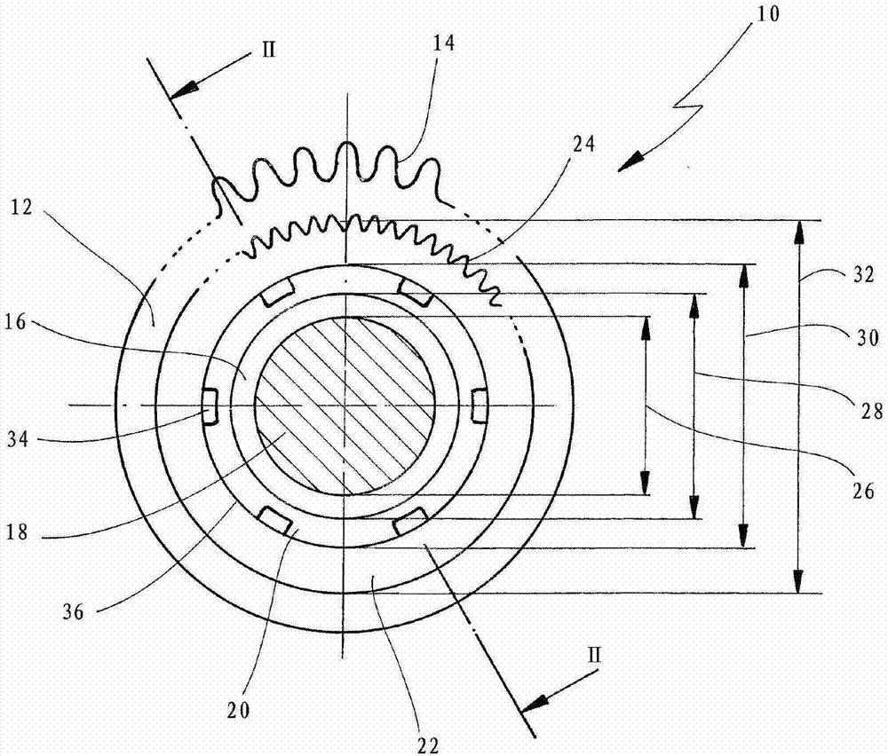
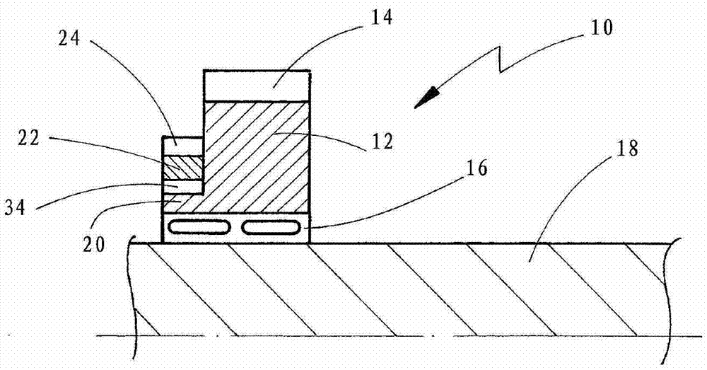
[0048] figure 1 and figure 2 A first embodiment of an idler arrangement made according to the first aspect of the invention is shown.
[0049] idler gear in figure 1 and figure 2 The center is indicated generally by reference numeral 10 and includes an idler (shift wheel) 12 with idler teeth 14 formed on the outer periphery of the idler. The idler gear teeth 14 can be designed as straight teeth, in particular the idler gear teeth 14 can be designed as helical teeth and configured to mesh with corresponding teeth of the fixed gear.
[0050] Idler 12 is rotatably mounted on shaft 18 via idler bearing 16 .
[0051] The idler gear 12 comprises a hub 20 protruding in the axial direction, wherein on the outer circumference of the hub 20 a clutch body 22 (which can be designed as a clutch disc or a clutch ring) is fastened. The clutch body 22 comprises on its outer circumference clutch body teeth 24 designed to mesh with internal teeth of the shift sleeve. The clutch body tee...
PUM
 Abstract
Description
Claims
Application Information