Device for adjusting the stroke of a tamping beam of a road finishing machine

A technology for repairing machines and tamping beams, which is applied in the field of stroke devices to achieve the effects of reducing wear, small amplitude and simple connection

Inactive Publication Date: 2016-06-15
BOMAG
View PDF7 Cites 0 Cited by
  • Summary
  • Abstract
  • Description
  • Claims
  • Application Information

AI Technical Summary

Problems solved by technology

The stroke can only be adjusted step by step in this way

Method used


Image

  • Device for adjusting the stroke of a tamping beam of a road finishing machine
  • Device for adjusting the stroke of a tamping beam of a road finishing machine
  • Device for adjusting the stroke of a tamping beam of a road finishing machine

Examples


Embodiment Construction

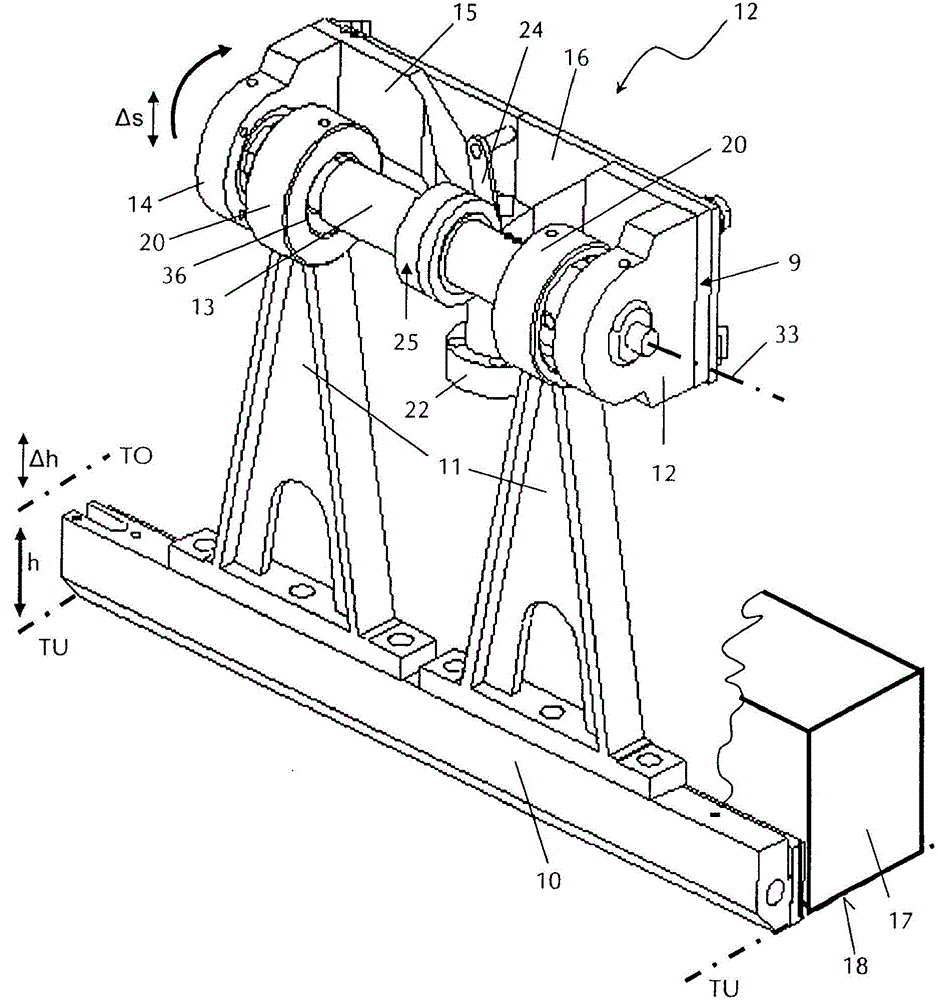
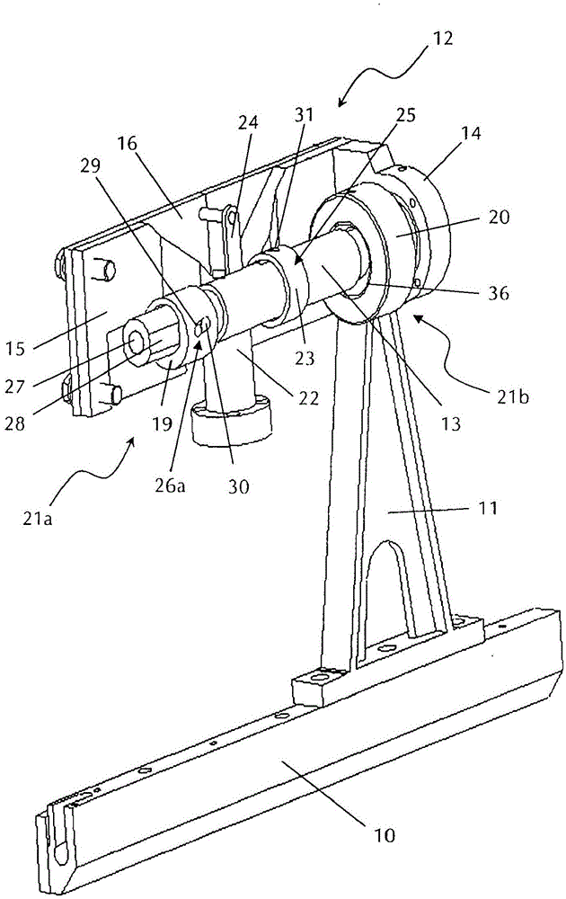
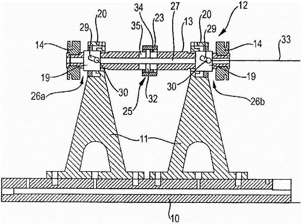
[0020] according to figure 1 and 2 , a tamping beam 10 of a road finishing machine (not shown) is connected to a mechanism 12 via two push rods 11 for adjusting the stroke of the tamping beam 10 . The mechanism 12 has a cam drive with a camshaft 13 fastened to a camshaft bracket 15 via a bearing block 14 . The camshaft bracket 15 is arranged displaceably in the height direction on a base frame 16 of a known paving screed (not shown) of the road finishing machine. Camshaft 13 is provided with two eccentric cams 19 ( figure 2 ), each eccentric cam 19 cooperates with the pivot cap 20 on the push rod 11 . The pivot cap 20 is provided with concentric bearing holes.

[0021] The paving screed has a slide 17 whose bottom surface 18 is substantially flat and which rests on the material to be paved. The tamping beam 10 is located in front of the slide 17 in the direction of travel of the road finishing machine. The tamping beam 10 , driven by the camshaft 13 , vibrates oscillati...


PUM


Abstract

The method involves arranging the tamping bar (10) by a cam shaft (13) having an eccentric cam (19) and a cam rotation axis (33). The reciprocating vertical oscillations of tamping bar are enabled between top dead center and bottom dead center. The eccentricity change of the eccentric cam is performed such that appropriate coercive eccentricity change of cam rotation axis for maintaining the bottom dead center is made. The cam rotational axis is displaced in the oscillation direction of the tamping bar while changing the cam shaft position. An independent claim is included for device for adjusting stroke of tamping bar of road finisher.

Description

technical field [0001] The invention relates to a device for adjusting the stroke of a tamping beam of a road finishing machine having a rotary drive mechanism for the tamping beam, wherein the tamping beam is set to pass through an eccentric adjustment mechanism and for adjusting The adjustment mechanism for the position of the camshaft in the vibration plane performs a vertical vibration with an upper dead center and a lower dead center. Background technique [0002] As is well known, road finishing machines are used to form road surfaces on flat surfaces. Spread the paving material, such as asphalt, over the desired pavement width before using the paving screed, and then use the screed to remove the paving material to the required thickness and smooth the pavement. A tamping beam (also known as a tamper) is positioned in front of the paving screed and uses a vertical tamping motion to compact the paving material and support the flow of the material to be paved beneath th...

Claims


Application Information

Patent Timeline
Patent Type & Authority Patents(China)
IPC IPC(8): E01C19/48
CPCE01C19/486
Inventor J·瓦格纳K-H·默茨
Owner BOMAG
Why Eureka
Try Eureka