Novel direct-connected single-stage pump

A single-stage pump, direct-connection technology, applied in non-variable-capacity pumps, pumps, pump devices, etc., can solve the problems of high production cost, unsightly, difficult disassembly and movement, etc., to meet the requirements of use, easy to implement and use. flexible effects

Inactive Publication Date: 2013-06-05
SHANGHAI LIANCHENG(GRP) CO LTD
View PDF7 Cites 1 Cited by
  • Summary
  • Abstract
  • Description
  • Claims
  • Application Information

AI Technical Summary

Problems solved by technology

[0002] The existing direct-coupled single-stage pump is composed of a pump body 11, an impeller 12, a pump cover 13, an extended shaft motor 14, and a base 15. It adopts the supporting structure at both ends of the motor casting foot and the pump casting foot (such as attached figure 1 shown), and the extended shaft structure with this whole shaft structure will have the following disadvantages: 1. This series of direct-coupled single-stage pumps has a rear door-opening structure. When repairing or replacing spare parts, the only way is to remove the motor. After removing the motor, the pump body can be disassembled for maintenance and replacement. If it is a larger pump set, it is very difficult to disassemble and move the high-power motor, which will increase the maintenance time and cost.
2. Since the supporting feet of this series of direct-coupled single-stage pumps are cast on the pump body, the outlet of the pump can only be installed vertically upward when viewed from the inlet direction of the pump set. If the installation direction of the pump outlet is to be left or right or rotated For a certain angle, the model of the pump body can only be modified, or the feet of the pump body can be cut off, and then welded on. The above method is time-consuming, labor-intensive, high in production cost, and not beautiful, which seriously affects the delivery speed and flexibility of use.

Method used


Image

  • Novel direct-connected single-stage pump
  • Novel direct-connected single-stage pump

Examples


Embodiment Construction

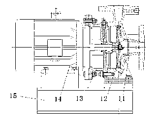
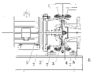
[0008] The figure includes a pump body, an impeller, a pump cover, a water inlet section, an extended shaft motor, and a base. The pump cover and the water inlet section are connected by studs, and the extended shaft motor is installed on one side of the pump cover. It is characterized in that: the pump cover, the water inlet section, and the feet under the extended shaft motor are all installed on a base.

[0009] The present invention is made up of pump body, impeller, pump cover, water inlet section, extended shaft motor, base, six parts. Casting feet are added to the water inlet section of the pump cover, and casting feet are removed from the pump body. The pump set is jointly supported by the motor feet, pump cover feet, and water inlet section feet. The pump body is connected by studs between the pump cover and the water inlet section, and the pump body can be rotated at any angle for assembly.

[0010] Moreover, the present invention is a front and rear door-opening s...


PUM


Abstract

The invention relates to a novel direct-connected single-stage pump which comprises a pump body, impellers, a pump cover, an inflow section, a lengthened shaft motor and a base. The novel direct-connected single-stage pump is characterized in that molten bottom feet are arranged on the pump cover and the inflow section, bottom feet are arranged under the lengthened shaft motor, the pump body is arranged between the pump cover and the inflow section, the pump cover and the inflow section are linked through double-screw bolts, and the lengthened shaft motor is arranged on one side of the pump cover. The novel direct-connected single-stage pump is characterized in that the pump cover, the inflow section, the bottom feet of the lengthened shaft motor are all arranged on the base. The novel direct-connected single-stage pump has the advantages that when a spare part is overhauled or exchanged, a user can not only conduct overhauling and exchanging by dismantling the motor to unlock the pump body, but also conduct overhauling and exchanging by dismantling the inflow section to unlock the pump body, and the pump body can be assembled by rotating at any angle. The novel direct-connected single-stage pump is simple in structure and easy to achieve, makes up shortage of the existing direct connection single stage pump and is capable of abundantly meeting requirements of a client on filed use.

Description

technical field [0001] The invention relates to a novel direct-connected single-stage pump mechanism. Background technique [0002] The existing direct-coupled single-stage pump is composed of a pump body 11, an impeller 12, a pump cover 13, an extended shaft motor 14, and a base 15. It adopts the supporting structure at both ends of the motor casting foot and the pump casting foot (such as attached figure 1 shown), and the extended shaft structure with this whole shaft structure will have the following disadvantages: 1. This series of direct-coupled single-stage pumps has a rear door-opening structure. When repairing or replacing spare parts, the only way is to remove the motor. Only after the motor is removed can the pump body be untied for maintenance and replacement. If a larger pump set is equipped with a high-power motor, it is quite difficult to disassemble and move, thereby increasing maintenance time and cost. 2. Since the supporting feet of this series of direct-...

Claims


Application Information

Patent Timeline
IPC IPC(8): F04D13/06F04D29/00
Inventor 田纯堂张锡淼
Owner SHANGHAI LIANCHENG(GRP) CO LTD
Why Eureka
Try Eureka