
Oil temperature control device of hydraulic system of paver

A technology of hydraulic system and oil temperature control, applied in the direction of fluid pressure actuating device, fluid pressure actuating system components, mechanical equipment, etc., can solve the problems of complex control, low efficiency and high cost, so as to improve work efficiency and high efficiency , the effect of low cost

Inactive Publication Date: 2013-06-05
SHAANXI JOINTARK MASCH GRP CO LTD
View PDF0 Cites 1 Cited by
  • Summary
  • Abstract
  • Description
  • Claims
  • Application Information

AI Technical Summary

Problems solved by technology

Hydraulic components only work in high-efficiency conditions when the oil temperature is within a certain range. In order to solve this problem, a technology that uses a variable displacement pump to drive a hydraulic motor to drive a fan has emerged, but this technology has high cost, complicated control and low efficiency.

Method used


Image

  • Oil temperature control device of hydraulic system of paver

Examples


Embodiment Construction

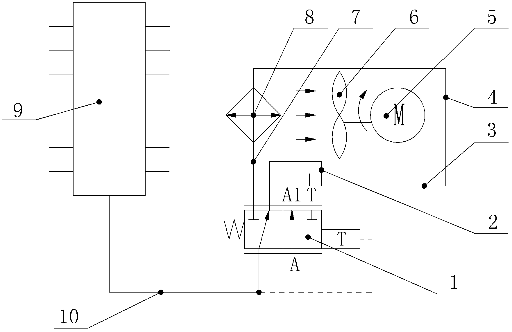
[0020] Such as figure 1 The oil temperature control device of a paver hydraulic system shown is characterized in that it includes an oil tank 3, a fan 6, an engine 5 that drives the fan 6 to rotate, a temperature control valve 1, a radiator 8, an oil return collection pipe 9, a pipe Road one 10, pipeline two 2, pipeline three 7 and pipeline four 4; the fan 6 that is used to cool the radiator 8 is connected with the engine 5, and one end of the pipeline one 10 is connected with the oil return oil collection pipe 9, so The other end of the pipeline one 10 is connected to the oil port A of the temperature control valve 1, one end of the pipeline two 2 is connected to the oil port T of the temperature control valve 1, and the other end of the pipeline two 2 is connected to the oil tank 3 One end of the pipeline three 7 is connected to the oil port A1 of the temperature control valve 1, the other end of the pipeline three 7 is connected to the oil inlet of the radiator 8, and one e...


PUM


Abstract

The invention discloses an oil temperature control device of a hydraulic system of a paver. The oil temperature control device of the hydraulic system of the paver comprises an oil tank, a fan, an engine, a temperature control valve, a radiator, an oil-return oil collecting pipe, a first pipe line, a second pipe line, a third pipe line and a fourth pipe line, wherein the fan is driven to rotate by the engine, the fan which is used for cooling the radiator is connected with the engine, one end of the first pipe line is connected with the oil-return oil collecting pipe, and the other end of the first pipe line is connected with an oil opening A of the temperature control valve, one end of the second pipe line is connected with an oil opening T of the temperature control valve, and the other end of the second pipe line is communicated with the oil tank, one end of the third pipe line is connected with an oil opening A 1 of the temperature control valve, and the other end of the third pipe line is connected with an oil inlet of the radiator, one end of the fourth pipe line is connected with an oil outlet of the radiator, and the other end of the fourth pipe line is communicated with the oil tank. The oil temperature control device of the hydraulic system of the paver is capable of basically achieving automatic constant temperature control of hydraulic oil temperatures of the hydraulic system of the paver.

Description

technical field [0001] The invention relates to an oil temperature control device, in particular to a paver hydraulic system oil temperature control device. Background technique [0002] The existing paver hydraulic system generally controls the oil temperature by forcing cooling regardless of the oil temperature. Hydraulic components only work in high-efficiency conditions when the oil temperature is within a certain range. In order to solve this problem, a technology that uses a variable displacement pump to drive a hydraulic motor to drive a fan has emerged. However, this technology has high cost, complicated control and low efficiency. How to develop an oil temperature control device with simple control, low technical cost and high efficiency is a technical problem to be solved urgently by those in the relevant technical field. Contents of the invention [0003] The object of the present invention is to overcome the shortcomings of the above-mentioned prior art and pr...

Claims


Application Information

Patent Timeline
Patent Type & Authority Applications(China)
IPC IPC(8): F15B21/04E01C19/12
Inventor 綦开隆王群锋
Owner SHAANXI JOINTARK MASCH GRP CO LTD
Learn More