
Tubular oil-head recovery shaft

A technology of oil receiver and tubular type, which is applied in the field of accessories for general oil receiver of tubular turbines, which can solve problems such as twisting of threaded parts and polished rod parts, and failure of normal operation of unit oil receivers, so as to avoid twisting , the effect of increasing strength and stiffness

Inactive Publication Date: 2013-06-05
TIANJIN TIRNFR HEAVY HYDROELECTRIC FRCILITY CO LTD
View PDF0 Cites 0 Cited by
  • Summary
  • Abstract
  • Description
  • Claims
  • Application Information

AI Technical Summary

Problems solved by technology

In this kind of connection, since the recovery shaft has both reciprocating and rotary motions, when the rotary motion of the recovery shaft is subject to frictional resistance, the connection between the threaded shaft head of the recovery shaft I and the polished rod is subject to the action of torque, which is likely to cause the threaded part and The polished rod is partially twisted, making the oil receiver of the unit unable to operate normally

Method used


Image

  • Tubular oil-head recovery shaft

Examples


Embodiment Construction

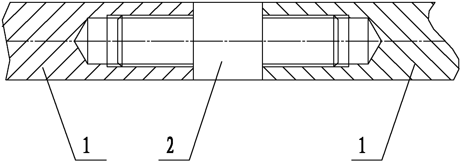
[0011] Such as figure 1 As shown, the present invention includes two recovery shafts 1 and a connecting shaft 2, the two ends of the connecting shaft 2 are provided with threaded shaft heads, one end of the recovery shaft 2 is provided with a threaded hole, and the two recovery shafts 1 and the two The connecting shaft 2 is screwed into one body.

[0012] The recovery shaft 1 is consistent with the maximum diameter of the connection shaft 2 .

[0013] After the recovery shaft 1 is screwed to the connection shaft 2, further welding is performed at the joint for fixing.

[0014] When installing, the connecting shaft 2 is first screwed with one of the recovery shafts 1, and then screwed with the other recovery shaft 1. After the recovery shaft 1 and the connecting shaft 2 are screwed together, the outer circle is welded to make it a whole. Increase the strength and rigidity, and avoid the twisting of the recovery shaft caused by the torque generated by the rotation.

[0015] A...


PUM


Abstract

The invention provides a tubular oil-head recovery shaft. The tubular oil-head recovery shaft comprises a recovery shaft and a connection shaft. Two ends of the connection shaft are provided with threaded shaft heads. An end of the recovery shaft is provided with a threaded hole. The recovery shaft is in a threaded connection relationship with the connection shaft. The tubular oil-head recovery shaft is an integral body, has high strength and high rigidity, and avoids recovery shaft twisting-off caused by a rotation torque.

Description

technical field [0001] The invention relates to the field of accessories for a universal oil receiver of a tubular water turbine, in particular to a recovery shaft of a tubular oil receiver. Background technique [0002] In the original tubular turbine, both the oil receiver and the main shaft operation oil pipe have the structure of the recovery shaft. Since the recovery shaft is too long, considering the convenience of transportation and installation, the recovery shaft is divided into several sections. When the power station is installed, several sections will be restored. The shafts are connected to become a shaft, which has both reciprocating motion and rotating motion with the runner of the water turbine when the unit is running. The connection between the two sections of shafts is threaded. One of the recovery shafts II has a threaded hole, and the other recovery shaft I has a threaded shaft head. After the two are connected, the outside is closed with bolts. In this...

Claims


Application Information

Patent Timeline
IPC IPC(8): F16C3/02F16D1/02F16D1/027F03B15/00
CPCY02E10/226Y02E10/20
Inventor 翟月敏周学均
Owner TIANJIN TIRNFR HEAVY HYDROELECTRIC FRCILITY CO LTD
Learn More