
Full Back Electrode Heterojunction Solar Cell

A solar cell, full-back electrode technology, applied in circuits, photovoltaic power generation, electrical components, etc., can solve the problems of large junction energy band difference, lower efficiency than expected, and high resistance, and achieve the effect of increasing open-circuit voltage and reducing short-circuit current.

Active Publication Date: 2016-06-29
IND TECH RES INST
View PDF6 Cites 0 Cited by
  • Summary
  • Abstract
  • Description
  • Claims
  • Application Information

AI Technical Summary

Problems solved by technology

[0005] However, this kind of full back electrode structure has the problem that the energy band difference of the element junction is too large, which leads to the problem of too high resistance, and the battery conversion efficiency is always not as expected.

Method used


Image

  • Full Back Electrode Heterojunction Solar Cell
  • Full Back Electrode Heterojunction Solar Cell
  • Full Back Electrode Heterojunction Solar Cell

Examples


Embodiment Construction

[0045] The present invention will be described in further detail below in conjunction with the accompanying drawings.

[0046] Please refer to the drawings to understand the present invention. However, the present invention can be implemented in many different forms and is not limited to the description of the embodiments. In the drawings, however, the sizes and relative sizes of layers and regions may not be drawn to scale for clarity.

[0047] When a member or layer is "located on another member or layer" herein, unless otherwise specified, it means that it may be directly located on another member or layer, or there may be an intermediate member or layer between the two. In addition, the text uses relative terms such as "on", "below" and similar spatial relative terms to describe the relationship between a component in the drawings and another (or more) components. However, the spatially relative terms may also include the orientation of the member in use or operation in a...


PUM


Abstract

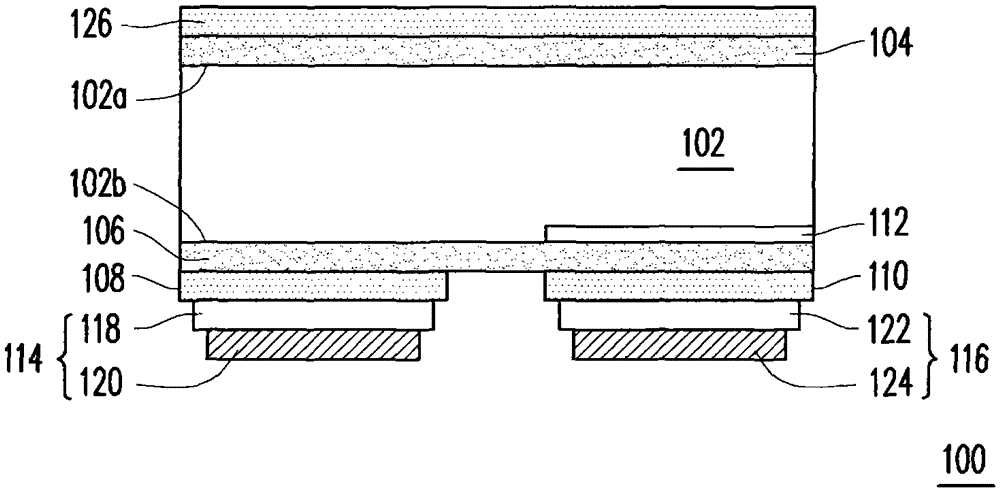
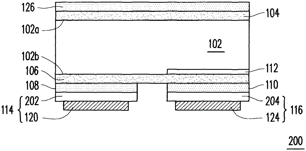
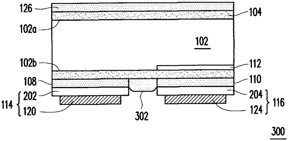
A full back electrode heterojunction solar cell, comprising a first conductivity type silicon substrate, a first amorphous semiconductor layer, a second amorphous semiconductor layer, a first conductivity type semiconductor layer, and a second conductivity type semiconductor layer and a second conductivity type doped region. The first amorphous semiconductor layer is located on the light-receiving surface of the silicon substrate, and is an intrinsic semiconductor layer or a first conductivity type layer. The second amorphous semiconductor layer is located on the non-light-receiving surface of the silicon substrate, wherein the second amorphous semiconductor layer is an intrinsic semiconductor layer. The first and second conductive type semiconductor layers are located on the second amorphous semiconductor layer respectively. As for the second conductive type doped region, it is located in the silicon substrate under the second conductive type semiconductor layer and contacts with the second amorphous semiconductor layer.

Description

technical field [0001] The present invention relates to a heterojunction solar cell, and in particular to a back-contactheterojunction solar cell. Background technique [0002] At present, high-efficiency solar cells are the trend of the future industry, because high-efficiency solar cells not only increase the power generation wattage per unit area, but also reduce costs. The deeper meaning is that they can increase the added value of module power generation. [0003] At present, the solar cell module with the highest efficiency in the world is SunPower's Interdigitated Back-Contact (IBC) full back-junction module, and its cell efficiency can exceed 24%. As far as the market is concerned, because of the above-mentioned high efficiency The solar cell manufacturing process is too cumbersome, and the cost of the manufacturing process is very high, so the manufacturing cost of the module is more than 50% higher than that of the traditional silicon module. [0004] Another type...

Claims


Application Information

Patent Timeline
Patent Type & Authority Patents(China)
IPC IPC(8): H01L31/0747
CPCH01L31/0682H01L31/0747Y02E10/547Y02E10/548
Inventor 吴德清萧睿中陈建勋林景熙丁密特·萨哈雷夫·丁密措夫
Owner IND TECH RES INST
Learn More