
Early identification of vortex ring state

An early identification and status technology, applied in rotorcraft, instruments, electrical digital data processing, etc., can solve problems such as uneconomical flight modes and uneconomical

Inactive Publication Date: 2016-10-12
国家航空航天研究办公室
View PDF2 Cites 0 Cited by
  • Summary
  • Abstract
  • Description
  • Claims
  • Application Information

AI Technical Summary

Problems solved by technology

However, this leads to uneconomical flying in many areas, which is gaining more and more importance today

Method used


Image

  • Early identification of vortex ring state
  • Early identification of vortex ring state
  • Early identification of vortex ring state

Examples


Embodiment Construction

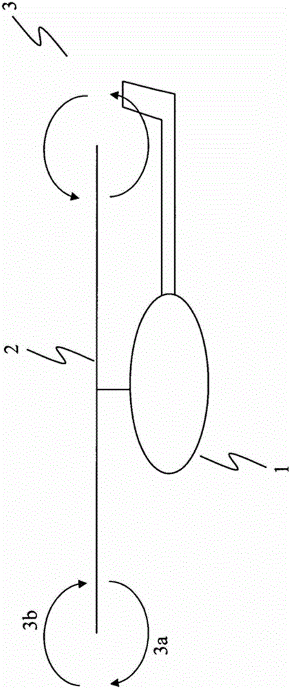
[0035] figure 1A diagrammatic representation of the vortex ring state 3 of the helicopter 1 is given. The helicopter 1 has a rotor 2 rotating with a corresponding rotational speed. Due to the slow or even no forward flight and the correspondingly high descent rate, the helicopter 1 enters its own downwash, so that the downwardly squeezed air 3 a cannot be expelled quickly enough. After a certain time this has the effect that the rotor 2 again absorbs the compressed air 3 a above the rotor (indicated by the arrow 3 b ), so that the compressed air 3 a is absorbed again. Here, a vortex ring 3 is formed around the tip of the rotor blade, and such a flying state is called a vortex ring state.

[0036] The problem here is that, due to the absorption of its own downwash flow field 3a, the lift force drops rapidly, and the helicopter will fall downward once at first. In this case, an altitude of several hundred meters is usually lost until the helicopter 1 can reach a normal flying...


PUM


Abstract

The invention relates to a method for early recognition of the state of a vortex ring of a helicopter, comprising the steps of determining a flight control signal for flight control with respect to the vertical axis of motion of the helicopter and detecting the resulting vertical motion of the helicopter Movement on the axis; early identification of the vortex ring state of the helicopter based on the correlation between the flight control signal and the vertical movement on the vertical axis of motion.

Description

technical field [0001] The invention relates to a method for early recognition of the state of a vortex ring of a helicopter. In addition, the invention also relates to a flight assistance system. [0002] Furthermore, the invention relates to a method for determining the speed of movement of a helicopter in a vertical axis of movement relative to the air surrounding the helicopter. The invention also relates to a flight assistance system. Background technique [0003] Helicopter systems are characterized by a rotor consisting of a plurality of rotor blades, which rotates at a defined speed. In this case, the individual rotor blades have a profile and are additionally fastened rotatably along the longitudinal axis on the rotor head of the rotor, so that during rotation a lift force is generated by the interaction of the rotor blade profile and the angle of attack (Anstellwinkel), This lift is similar to that of a fixed wing aircraft. [0004] Due to the lift force caused...

Claims


Application Information

Patent Timeline
Patent Type & Authority Patents(China)
IPC IPC(8): B64C27/00G05B23/02
CPCB64C27/006G06F17/00
Inventor M.阿比尔德加德L.比内特
Owner 国家航空航天研究办公室
Learn More