Highly-efficient energy-saving engine and application thereof
A high-efficiency, energy-saving, engine technology, applied in engine components, combustion engines, machines/engines, etc., can solve the problems of low energy utilization, short piston stroke, low work efficiency, etc., to achieve high energy utilization and increase output power. , the effect of increasing the working ability
- Summary
- Abstract
- Description
- Claims
- Application Information
AI Technical Summary
Problems solved by technology
Method used
Image
Examples
Embodiment 1
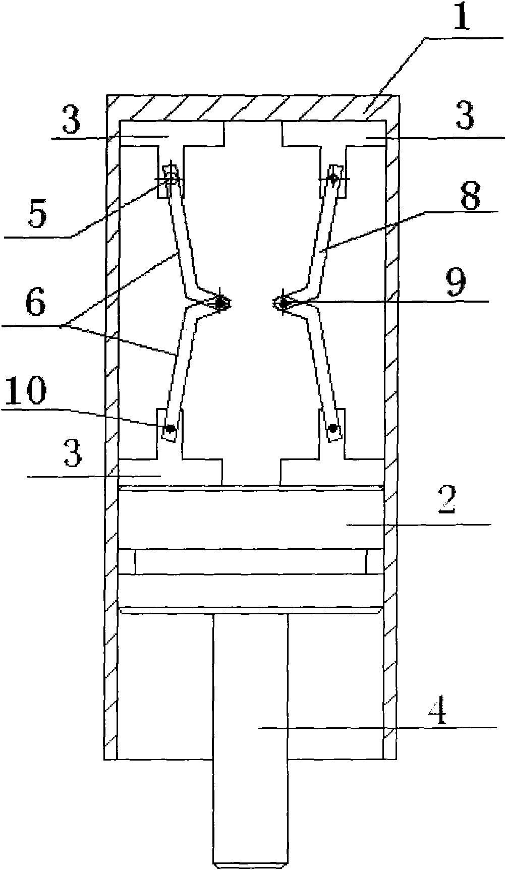
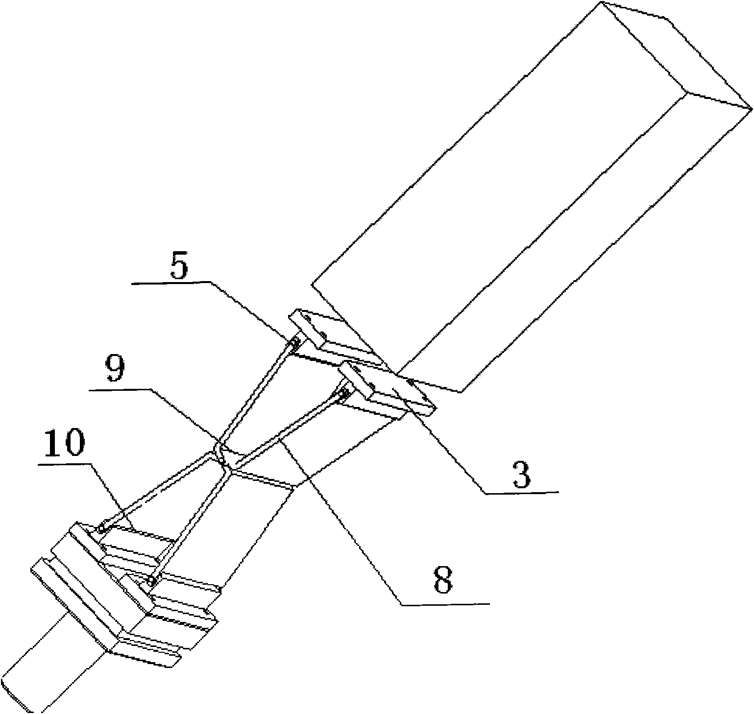
[0034] figure 1 It is a structural schematic diagram of a high-efficiency and energy-saving engine of the present invention, figure 2 It is a schematic diagram of enlarged and decomposed structure of a high-efficiency energy-saving engine part of the present invention, such as figure 1 , 2 Shown:
[0035] A high-efficiency and energy-saving engine, the top of a cylinder 1 and the top of a piston 2 are respectively fixed with two supports 3 . The concave movable connection ends 9 of the two L-shaped brackets 8 are connected by the shaft 5 to form a hinge link 6, and two pairs of hinge links 6 form a hinge link mechanism, and the hinge link mechanism passes through two pairs of hinge links. The concave movable connection end 10 of 6 is movably connected with the support 3 through the shaft 5 .
[0036] Wherein, the concave movable connection ends 9 of the two L-shaped brackets 8 face inward.
[0037] When the engine starts to work, the piston 2 moves upward from the bottom...
Embodiment 2
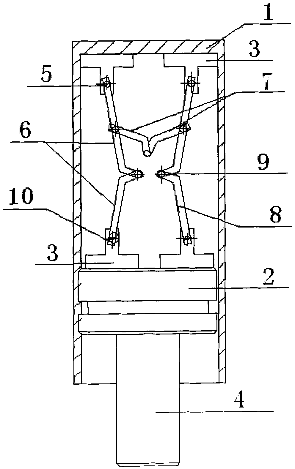
[0039] image 3 It is a structural schematic diagram of an embodiment of a high-efficiency and energy-saving engine of the present invention, as image 3 Shown:
[0040] A high-efficiency and energy-saving engine, the top of a cylinder 1 and the top of a piston 2 are respectively fixed with two supports 3 .
[0041] The hinge link mechanism is composed of two pairs of hinge links 6 and a pair of hinge links 7 . The concave movable connection ends 9 of the two L-shaped brackets 8 are connected through the shaft 5 to form the hinge connecting rod 6, and the concave movable connection ends 10 of the two pairs of hinge connecting rods 6 are respectively movable connected to the cylinder 1 and the piston 2 through the shaft 5. The connecting ends of the two supports 3 on the top; the hinge link 7 is movably connected to the middle part of the L-shaped support of the two pairs of hinge links 6 through the shaft to form a hinge link mechanism.
[0042] Wherein, the concave movable...
Embodiment 3
[0045] Figure 4 It is a structural schematic diagram of an embodiment of a high-efficiency and energy-saving engine of the present invention, as Figure 4 Shown:
[0046] A high-efficiency and energy-saving engine, the top of a cylinder 1 and the top of a piston 2 are respectively fixed with two supports 3 .
[0047] The hinge link mechanism is composed of two pairs of hinge links 6 and two hinge pieces 11 . The concave movable connection ends 9 of the two L-shaped brackets 8 are connected through the shaft 5 to form the hinge connecting rod 6, and the concave movable connection ends 10 of the two pairs of hinge connecting rods 6 are respectively movable connected to the cylinder 1 and the piston 2 through the shaft 5. The connection ends of the two supports 3 on the top; the concave movable connection ends 12 of the two connecting rods are movably connected with the connection ends of the supports 3 fixed on the top of the cylinder 1 through the shaft 5, and the two hinges...
PUM
 Abstract
Description
Claims
Application Information
 - R&D
- Intellectual Property
- Life Sciences
- Materials
- Tech Scout
- Unparalleled Data Quality
- Higher Quality Content
- 60% Fewer Hallucinations
Browse by: Latest US Patents, China's latest patents, Technical Efficacy Thesaurus, Application Domain, Technology Topic, Popular Technical Reports.
© 2025 PatSnap. All rights reserved.Legal|Privacy policy|Modern Slavery Act Transparency Statement|Sitemap|About US| Contact US: help@patsnap.com


