Heat-punching composite mould

A hot stamping die and hot stamping technology, applied in the field of hot stamping, can solve the problems of not considering the influence of cooling pipes and large limitations.

Active Publication Date: 2013-06-12
ADVANCED MFG TECH CENT CHINA ACAD OF MASCH SCI & TECH
View PDF5 Cites 11 Cited by
  • Summary
  • Abstract
  • Description
  • Claims
  • Application Information

AI Technical Summary

Problems solved by technology

The mold disclosed in this patent is composed of upper and lower molds and upper and lower punching tools, not a set of composite molds; in addition, the mold does not consider the influence of cooling pipes on the upper and lower punching tools, so it has great limitations

Method used


Image

  • Heat-punching composite mould
  • Heat-punching composite mould

Examples


Embodiment Construction

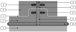
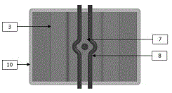
[0016] exist figure 1 In the front view of the schematic diagram of the hot stamping composite die shown, a hot stamping composite die consists of a lower mold base (1), a forming punch (2), a hot stamping part (3), a forming die (4), and a forming die Die cooling system (5), punching die (6), punching waste (7), forming punch cooling system (8), punching punch (9), rubber (10). The composite mold is connected with the press by the lower mold base (1), the lower mold base (1) and the forming punch (2) and the punching punch (9) transmit power through the rubber (10), and the forming punch (2) and the forming The hot stamping part (3) is molded by the mold closing of the die (4), and the holes on the hot stamping part are punched out by the punching punch (9) and the punching die (6). By passing cooling water into the forming die cooling system (5) and forming punch cooling system (8), the mold is forced to cool, so that the hot stamping composite mold can be kept within the n...


PUM


Abstract

By casting and processing a heat-punching mould, a complex cooling system can be embedded into the heat-punching mould, in order to avoid the limitation brought to the heat-punching mould by a drilling process, the heat-punching mould with more complete functions can be designed, the heat-punching mould is designed to be a heat-punching composite mould, and functions of shaping, punching, quenching and the like are integrated. According to a design concept of the heat-punching composite mould, the heat-punching composite mould is designed according to the structure and the shape of a heat-punching piece, on the basis of the structures of the heat-punching piece and a mould, the cooling system is designed, and the best design scheme is obtained by optimization. A manufacture process of the heat-punching composite mould is that firstly the cooling system of the heat-punching mould is processed through the processing of a pipeline bending, then the cooling system is embedded into the heat-punching mould via casting, and finally the heat-punching composite mould is obtained according to machinery processing, heat treatment and assembly.

Description

technical field [0001] This patent belongs to the technical field of hot stamping, and mainly relates to the design and manufacturing method of hot stamping dies. Background technique [0002] The lightweight of automobiles promotes the rapid development of ultra-high-strength steel hot stamping technology. The hot stamping die is the core component of the hot stamping production line. Its function is to complete the forming and quenching of the hot stamping parts during the hot forming process. Therefore, it is necessary to process a cooling system in the mold to increase the cooling speed and complete the hot stamping parts immediately. body transformation. [0003] At present, the cooling system of the hot stamping die is mainly processed by drilling, so the die structure and cooling system are limited by the processing method, and cannot be designed as a hot stamping composite die. The hot stamping die can only realize the forming and quenching functions, not For punch...

Claims


Application Information

Patent Timeline
Patent Type & Authority Applications(China)
IPC IPC(8): B21D37/10
Inventor 单忠德叶永盛蔡万华姜超闫沁太贾瑞鹏
Owner ADVANCED MFG TECH CENT CHINA ACAD OF MASCH SCI & TECH
Why Eureka
Try Eureka