Laminator

A film laminating machine and film technology, which is applied in the direction of lamination device, lamination auxiliary operation, lamination, etc., can solve the problems of accuracy reduction, image deviation, rotation seat 121 occupancy, etc., and achieve the effect of reducing volume

Inactive Publication Date: 2013-06-12
EFUN TECH CO LTD
View PDF7 Cites 10 Cited by
  • Summary
  • Abstract
  • Description
  • Claims
  • Application Information

AI Technical Summary

Problems solved by technology

[0008] 1. The rotating seat 121 is intermittently rotating to transmit the first film 101. The first film 101 must sequentially pass through the release position 124, the cleaning position 125, the empty position 126, and the bonding position 127, so it will The process time is extended, and the rotating seat 121 must occupy a large space for rotation to perform different processes at different positions. Therefore, the structure and process design of the film sticking equipment 1 still need to be improved.
[0009] 2. The first image picker 161 is installed on the moving seat 141. However, during the process of transferring the second film 102, the moving seat 141 must move up and down and then move left and right. That is to say, the moving seat 141 is a moving This will lead to deviations in the image captured by the first image capture device 161, and the accuracy will be reduced, often resulting in the consequence of misalignment, and the defect rate remains high. In addition to the need to frequently calibrate the first image capture device 161 In addition, the first image capture device 161 is also prone to malfunction, has a short service life and poor usability

Method used


Image

  • Laminator
  • Laminator
  • Laminator

Examples


Embodiment Construction

[0029] Below in conjunction with accompanying drawing and embodiment the present invention is described in detail:

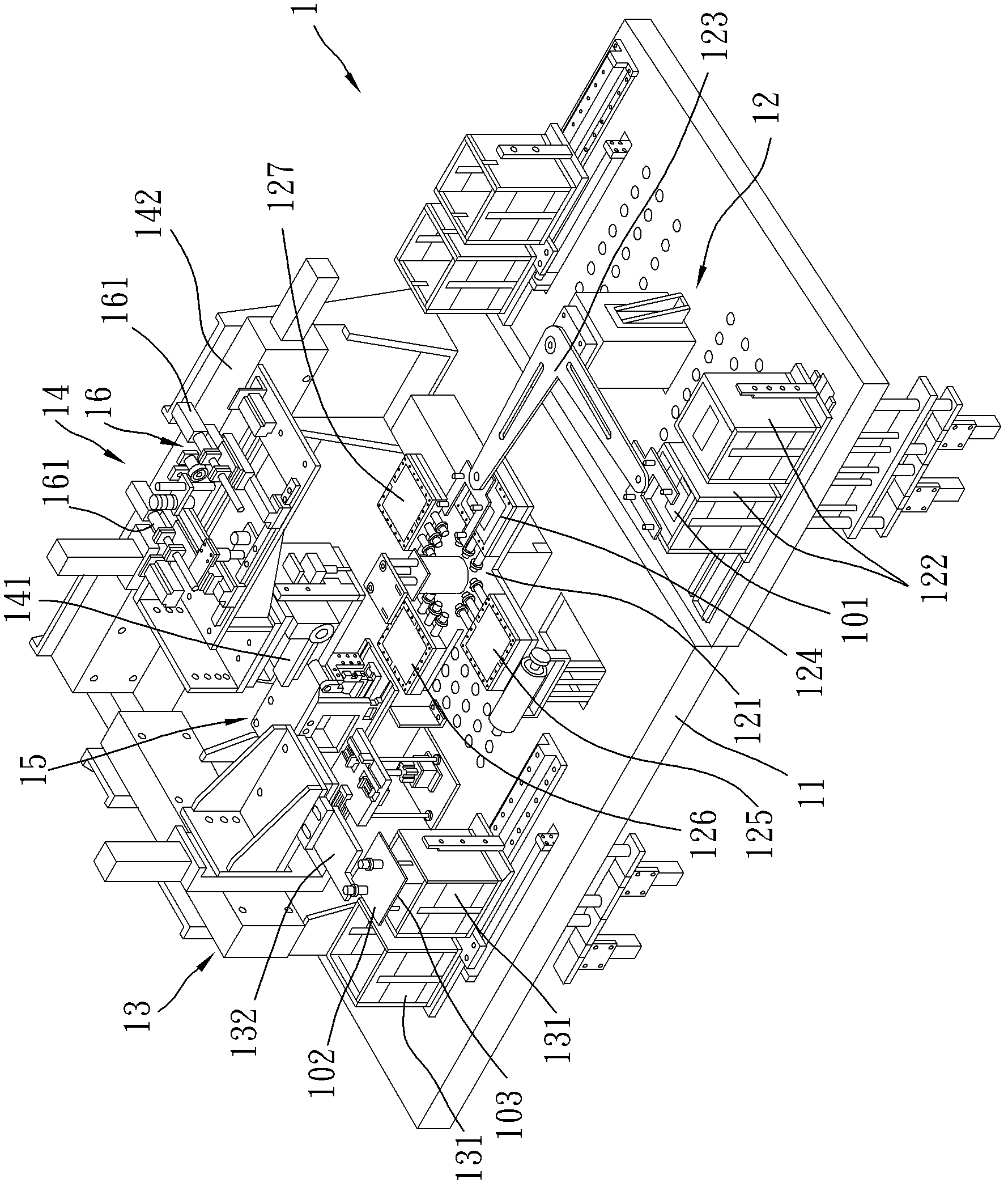
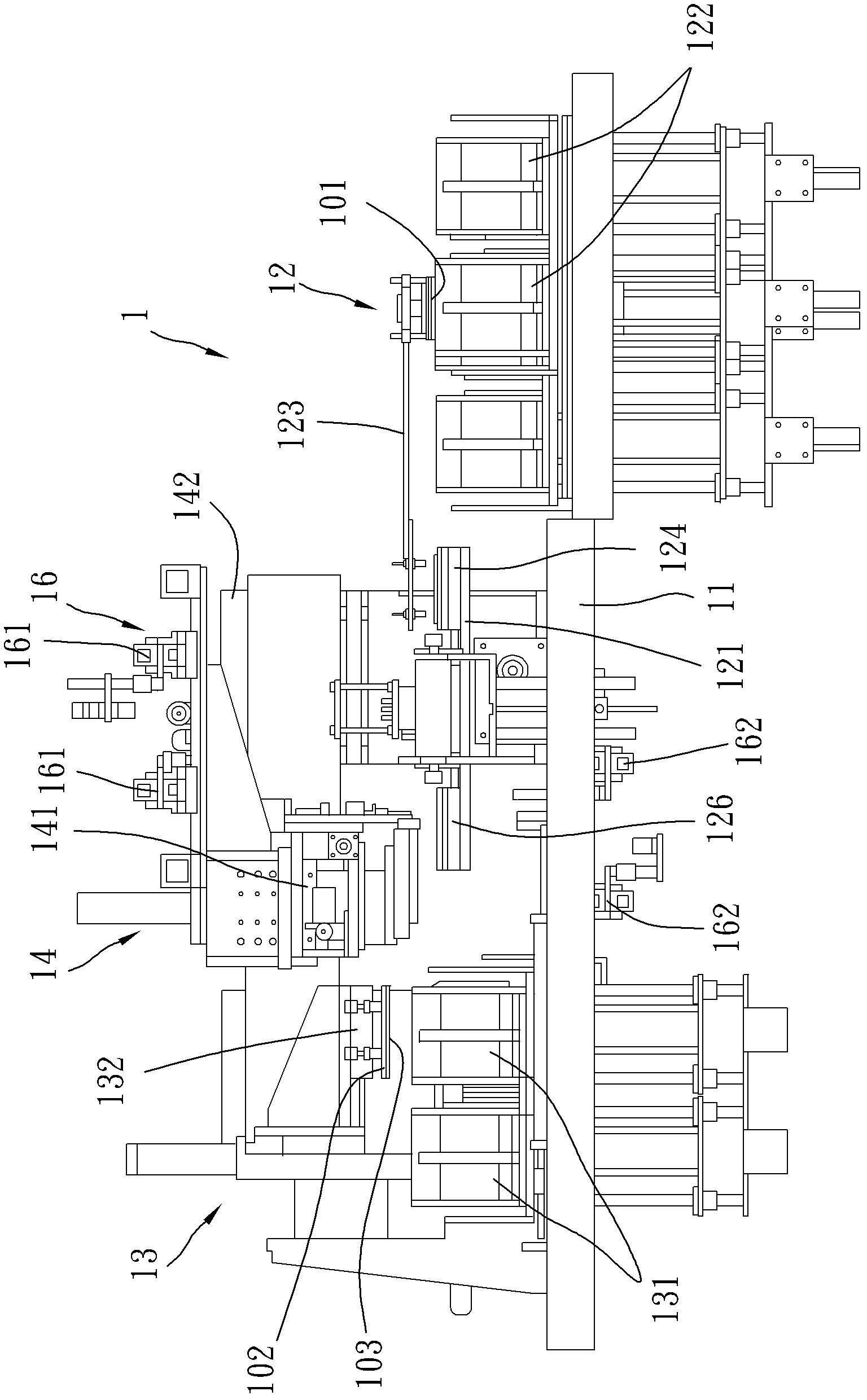
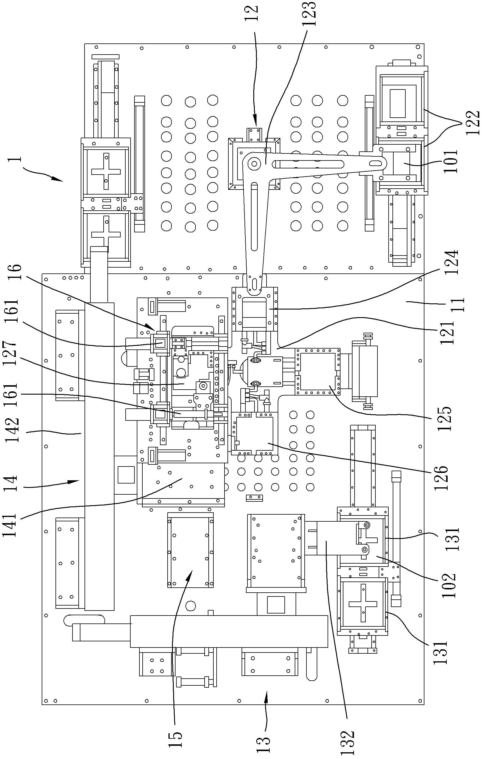
[0030] refer to Figure 4 , Figure 5 and Image 6 , a preferred embodiment of the film laminating machine of the present invention can quickly and high-yield paste multi-layer films such as touch panels, backlight modules or other optical plates. In this embodiment, a piece of first film 21 and A piece of second membrane 22 and a piece of peelable protective film 23 attached to the bottom of the second membrane 22 are used as an example for illustration, and of course the implementation is not limited thereto.

[0031] The film laminating machine includes: a machine platform 3, and a first conveying device 4, a second conveying device 5, a film-separating device 6, a third conveying device 7 and an adjusting device 8 installed on the machine platform 3 . The directions shown in the figures are used for illustration below, and of course, the implementation d...


PUM


Abstract

The invention relates to a laminator. The laminator includes a machine table, and a first conveying device, a third conveying device and an adjusting device which are mounted on the machine table. The first conveying device is used for carrying a first film, and is linearly movable and is installed on the machine table in an adjustable angle. The third conveying device is used for conveying a second film to the first conveying device to fit with the first film. The adjusting device includes a first image capture unit and a second image capture unit which are fixedly arranged on the machine table and are used for respectively capturing the image of the first film and the image of the second film. With the above structure, the laminator provided by the invention takes little space, and has the effect of fitting accurately and quickly.

Description

technical field [0001] The invention relates to a film laminating machine, in particular to a film laminating machine for pasting two film sheets. Background technique [0002] refer to figure 1 , figure 2 and image 3 , a film sticking device 1 disclosed in Taiwan Patent Application No. 098133126, China, is used to stick a piece of first film 101 and a piece of second film 102, and the bottom of the second film 102 is covered with a tearable The separated protective film 103, and includes: a machine platform 11, a first conveying device 12 for conveying the first film 101, a second conveying device 13 for conveying the second film 102, a second conveying device 102 for conveying the second film 102 To the first conveying device 12 and the third conveying device 14 bonded to the first film 101, a film separation device 15 installed between the second conveying device 13 and the third conveying device 14, and a capture and compare An image capturing device 16 for images ...

Claims


Application Information

Patent Timeline
Patent Type & Authority Applications(China)
IPC IPC(8): B32B37/00B32B38/00
Inventor 唐世杰王启任黄春贵
Owner EFUN TECH CO LTD
Why Eureka
Try Eureka