Magnetorheological flow control valve

A flow control valve and magneto-rheological technology, applied in the direction of valve details, valve devices, valve operation/release devices, etc., can solve the problems that the flow control cannot be changed, it is difficult to realize stepless control, and the product consistency is poor. The effect of simple structure, wide range and large pressure range

Active Publication Date: 2013-06-12
JILIN UNIV
View PDF5 Cites 7 Cited by
  • Summary
  • Abstract
  • Description
  • Claims
  • Application Information

AI Technical Summary

Problems solved by technology

Traditional flow control valves design multiple different flow areas through mechanical design, and control different flows through switching. The disadvantages are: high machining accuracy requirements and poor product consistency; switching requires the design of auxiliary structures, resulting in complex structures ;Once the design is completed, the flow control cannot be changed, and it is difficult to achieve stepless control

Method used


Image

  • Magnetorheological flow control valve
  • Magnetorheological flow control valve

Examples


Embodiment Construction

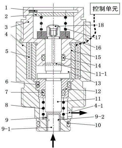
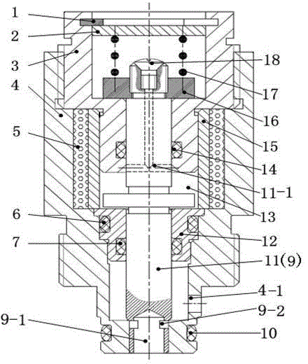
[0011] attached by figure 1 As shown: the magnetorheological flow control valve includes: circlip 1, upper end cover 2, upper valve body 3, lower valve body 4, coil 5, lower thrust spring 8, valve core 9, thrust shaft 11, inner valve body 12 , working cavity 13, magnetic isolation sleeve 15, spring seat 16, upper thrust spring 17, sealing bolt 18 and multiple rubber sealing rings (6, 7, 10, 14). The upper end cover 2 is set inside the upper valve body 3, the upper end of the upper end cover 2 is provided with a retaining spring 1, and the lower end is provided with an upper thrust spring 17 in a compressed state, so that the relative position between the upper end cover 2 and the upper valve body 3 fixed. The lower end of the upper thrust spring 17 is arranged on the spring seat 16, and the spring seat 16 is fixed on the uppermost end of the thrust shaft 11 through threaded connection, and a rubber sealing ring 14 is arranged between the thrust shaft 11 and the upper valve bo...


PUM


Abstract

The invention relates to a flow control valve, in particular to a magnetorheological flow control valve which realizes flow control through the opening degree of the control valve. The flow control valve comprises a jump ring, an upper end cover, an upper valve body, a lower valve body, a coil, a lower thrust spring, a valve core, a thrust shaft, an inner valve body, a working cavity, a magnetic isolation sleeve, a spring seat, an upper thrust spring, a seal bolt and a plurality of rubber seal rings; and according to the magnetorheological flow control valve, the shifting position of the valve core is controlled through a technical method in which the magnetic field intensity which acts on magnetorheological fluid in the working cavity formed between the magnetic isolation sleeve and the upper valve body is controlled, so that the magnetorheological fluid yield strength is affected and the action force of magnetorheological fluid to the thrust shaft is controlled, so that different circulation areas are obtained and the the control over the fluid flow is realized.

Description

technical field [0001] The invention relates to a flow control valve, in particular to a magneto-rheological flow control valve which realizes flow control by controlling the valve opening. Background technique [0002] Common flow control valves usually control the flow of fluid by controlling the flow area of ​​the channel. Traditional flow control valves design multiple different flow areas through mechanical design, and control different flows through switching. The disadvantages are: high machining accuracy requirements and poor product consistency; switching requires the design of auxiliary structures, resulting in complex structures ; Once the design is completed, the flow control cannot be changed, and it is difficult to achieve stepless control. With the development of technology, the flow control valve is required to develop in the direction of miniaturization, intelligence and economy. This requires the control structure of the flow control valve to the flow area...

Claims


Application Information

Patent Timeline
Patent Type & Authority Applications(China)
IPC IPC(8): F16K31/06F16K31/12
Inventor 章新杰郭弓郑福淼郭孔辉杨杰
Owner JILIN UNIV
Why Eureka
Try Eureka