
A wireless piezoelectric lighter

A lighter and piezoelectric technology, which is applied in the direction of combustion ignition, igniter with fuel, combustion method, etc., can solve the problems of low efficiency, complicated operation, and unannounced wireless piezoelectric components, so as to shorten the assembly process and improve production Efficiency and the effect of reducing manufacturing costs

Active Publication Date: 2015-08-19
XINHAI TECH GRP CO LTD
View PDF10 Cites 0 Cited by
  • Summary
  • Abstract
  • Description
  • Claims
  • Application Information

AI Technical Summary

Problems solved by technology

[0002] The piezoelectrics used in existing lighters are basically wired piezoelectrics. There are wires inside the wired piezoelectric components. Due to the existence of the wires, the wired piezoelectric components are complicated to operate when they are installed in the lighter, and it is difficult to realize automatic assembly. After installation The length and position of the wires in the piezoelectric component are not very accurate, and workers are required to trim and adjust the length and position of the wires in the piezoelectric component, which is inefficient; currently there are Chinese patents for wireless piezoelectric components, such as the one with the patent number 201020174423.2 A piezoelectric ignition device, but the patent does not disclose the structure of applying wireless piezoelectric components to lighters

Method used


Image

  • A wireless piezoelectric lighter

Examples


Embodiment 1

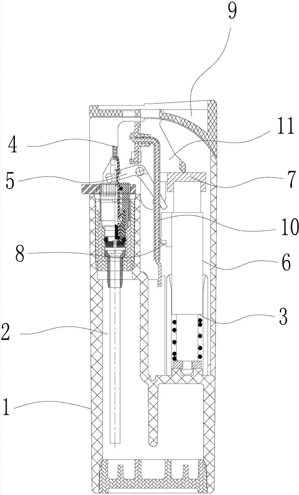
[0015] Such as figure 1 As shown, a wireless piezoelectric lighter described in this embodiment includes a housing 1, an oil tank 2 placed in the housing, a piezoelectric assembly 3 and an air outlet assembly 4, and the air outlet assembly 4 includes an air outlet valve, an air outlet and The crowbar 5 that controls the opening and closing of the air outlet valve, the piezoelectric assembly 3 is a wireless piezoelectric assembly and includes a piezoelectric housing 6 that can move up and down, a conductive cap 7 that is fixed on the top of the piezoelectric housing, and a conductive cap that is fixed on the pressure The piezoelectric electrode 8 outside the electric casing, the conductive cap 7 and the piezoelectric electrode 8 move up and down with the piezoelectric casing 6, and the conductive cap 7 is provided with a pressing hand that can drive the piezoelectric casing 6 to move up and down and the crowbar 5 to rotate. 9. When the pressing hand 9 is pressed down, it direct...


PUM


Abstract

The invention discloses a wireless piezoelectric lighter, which solves the technical problem that the existing lighters are all wired piezoelectric assemblies, so the assembly is troublesome. The wireless piezoelectric lighter comprises a casing, an oil groove, a piezoelectric assembly and a gas outlet assembly, wherein the oil groove is arranged in the casing, the gas outlet assembly comprises a gas outlet valve, a gas outlet and a prizing plate, and the prizing plate controls the opening and the closing of the gas outlet valve. The wireless piezoelectric lighter is characterized in that the piezoelectric assembly is the wireless piezoelectric assembly and comprises a piezoelectric case, a conducting cap and a piezoelectric electrode, the piezoelectric case can vertically displace, the conducting cap is fixedly connected with the top of the piezoelectric case, the piezoelectric electrode is fixedly connected with the outside of the piezoelectric case, and a lifting handle capable of driving the piezoelectric case to do vertical displacement and driving the prizing plate to rotate is arranged above the conducting cap. The wireless piezoelectric lighter adopts the wireless piezoelectric assembly, a conducting wire does not need to be used in the piezoelectric assembly for conduction, a casing made of conducting plastics is not needed, the structure is simplified, the assembly flow process of the lighter is shortened, and the production efficiency can be greatly improved, so the manufacture cost is reduced.

Description

technical field [0001] The invention relates to the field of lighters, in particular to a wireless piezoelectric lighter. Background technique [0002] The piezoelectrics used in existing lighters are basically wired piezoelectrics. There are wires inside the wired piezoelectric components. Due to the existence of the wires, the wired piezoelectric components are complicated to operate when they are installed in the lighter, and it is difficult to realize automatic assembly. After installation The length and position of the wires in the piezoelectric component are not very accurate, and workers are required to trim and adjust the length and position of the wires in the piezoelectric component, which is inefficient; currently there are Chinese patents for wireless piezoelectric components, such as the one with the patent number 201020174423.2 A piezoelectric ignition device, but this patent does not disclose the structure of applying wireless piezoelectric components to light...

Claims


Application Information

Patent Timeline
Patent Type & Authority Patents(China)
IPC IPC(8): F23Q2/28F23Q2/34
Inventor 黄新华胡直
Owner XINHAI TECH GRP CO LTD
Learn More