Micro-incline generation device for field proving of clinometer

A technology for on-site calibration and device generation. It is applied to measurement devices, instruments, etc. It can solve the problem that the parameters and sensitivity of the instrument cannot be calibrated again, and achieve the effect of convenient operation and time saving.

Active Publication Date: 2013-06-12
INST OF EARTHQUAKE CHINA EARTHQUAKE ADMINISTRATION +1
View PDF2 Cites 5 Cited by
  • Summary
  • Abstract
  • Description
  • Claims
  • Application Information

AI Technical Summary

Problems solved by technology

[0009] 2. The inclinometer can only be calibrated once at the factory, even if the instrument param

Method used


Image

  • Micro-incline generation device for field proving of clinometer
  • Micro-incline generation device for field proving of clinometer

Examples


Embodiment Construction

[0045] Below in conjunction with accompanying drawing and embodiment describe in detail:

[0046] 1. The structure of this device

[0047] 1. Overall

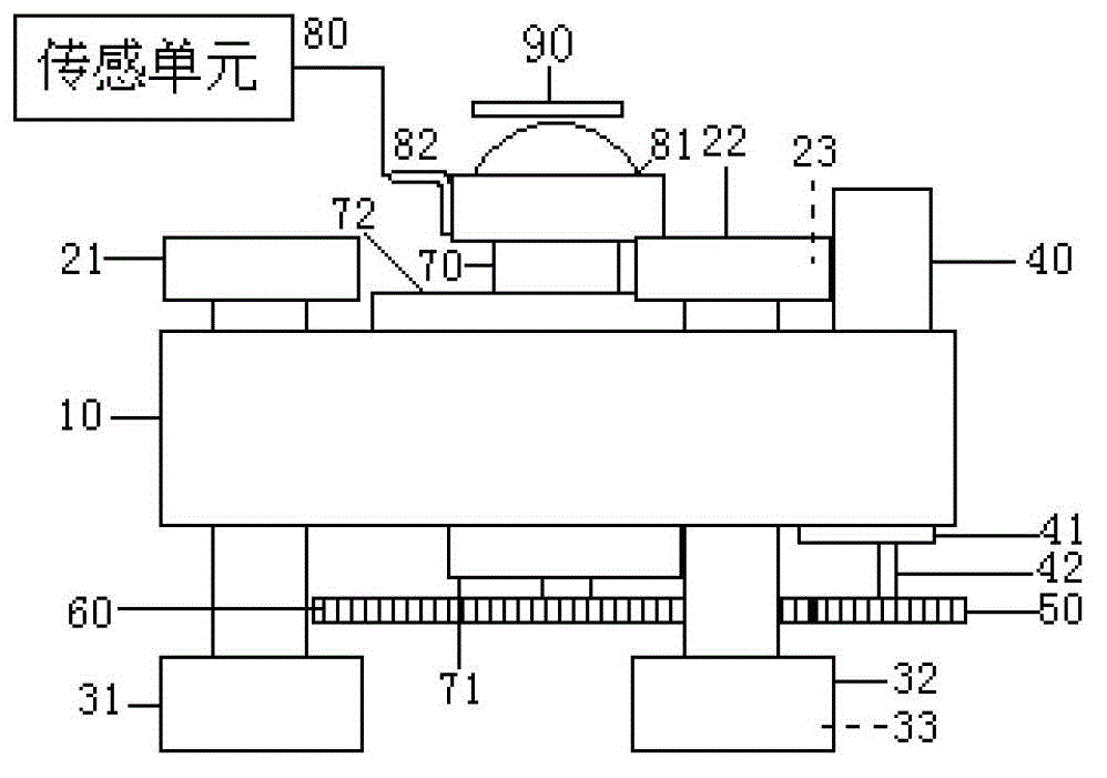
[0048] Such as figure 1 , the device consists of a base 10, a supporting screw 20, a pad 30, a DC motor 40, a driving gear 50, a driven gear 60, piezoelectric ceramics 70, a sensing unit 80 and a contact piece 90;

[0049] The supporting screw 20 includes a first screw 21, a second screw 22 and a third screw 23;

[0050] The spacer 30 includes a first spacer 31, a second spacer 32 and a third spacer 33;

[0051] The first screw rod 21, the second screw rod 22 and the third screw rod 23 arranged in a triangle pass through the screw holes of the base 10 respectively and placed on the corresponding first spacer 31, the second spacer 32 and the third spacer arranged in a triangle On the block 33, a working platform is formed;

[0052] The DC motor 40 is arranged on the base 10 through the fixed piece 41, the rotating shaft 42...


PUM


Abstract

The invention discloses a micro-incline generation device for field proving of a clinometer, and relates to a geological instrument proving technique. The device consists of a base, support screw rods, cushion blocks, a direct-current motor, a driving gear, a driven gear, piezoelectric ceramic, a sensing unit and a touch sheet. The method comprises the following steps of: (1) coarsely tuning for the first time; (2) coarsely tuning for the second time; (3) finely tuning by utilizing the piezoelectric ceramic 70; (4) measuring micro displacement of the clinometer through a precision displacement measuring meter; and (5) calculating the angle variation of the clinometer by the micro displacement, and comparing the angle variation of the clinometer with the output voltage variation of the clinometer, thereby obtaining a scale value. The micro-incline generation device for field proving of the clinometer provided by the invention has a small volume, is convenient to carry, is convenient to operate, saves time, is compatible with proving, and is suitable for proving the clinometer.

Description

technical field [0001] The invention relates to a calibrating device for geoscience instruments, in particular to a micro-tilt generating device for field calibrating an inclinometer. Background technique [0002] The tiltmeter is an instrument used to observe the tilt of the earth, and is suitable for observing solid tides and slow earthquakes. [0003] At the end of the seventeenth century, when Newton discovered the law of universal gravitation and used it to explain tidal phenomena, people imagined that the tidal force of the sun and moon would cause the direction of the plumb line to change. At that time, many people tried to measure the change of the tidal force of the sun and the moon on the equilibrium position of the free-hanging plumb pendulum, and did a lot of experiments, but all failed due to insufficient measurement sensitivity. It was not until the German Hengler invented the horizontal pendulum in the 19th century, and the displacement was magnified many tim...

Claims


Application Information

Patent Timeline
IPC IPC(8): G01C25/00
Inventor 胡国庆马武刚吴艳霞邹舟谭业春吴涛
Owner INST OF EARTHQUAKE CHINA EARTHQUAKE ADMINISTRATION
Why Eureka
Try Eureka