
Micro-flow detection method based on recognition of droplet images at pipeline outlet

A technology of image recognition and detection methods, applied in liquid/fluid solid measurement, measurement flow/mass flow, measurement devices, etc., to achieve low-cost effects

Inactive Publication Date: 2013-06-12
ZHEJIANG UNIV
View PDF5 Cites 6 Cited by
  • Summary
  • Abstract
  • Description
  • Claims
  • Application Information

AI Technical Summary

Problems solved by technology

[0004] However, for microchemical devices, since their physical scale is often millimeter, submillimeter or even micron, how to realize the detection of process parameters such as flow rate in an extremely narrow physical space is an urgent need in the practical application of microchemical industry. important problems to solve

Method used


Image

  • Micro-flow detection method based on recognition of droplet images at pipeline outlet
  • Micro-flow detection method based on recognition of droplet images at pipeline outlet
  • Micro-flow detection method based on recognition of droplet images at pipeline outlet

Examples


Embodiment 1

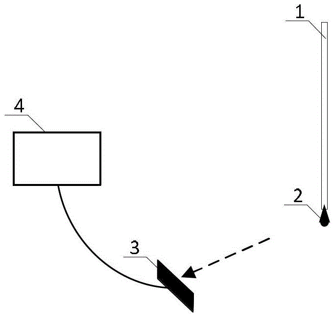
[0031] Embodiment 1 is a single-pipeline micro-flow detection device, such as figure 1 As shown, the detection device is composed of a camera or a camera 3 , a computer or an electronic computing device 4 .

[0032] In the pipeline outlet section 1, the liquid flows from top to bottom and forms a droplet 2 at the outlet of the pipeline. The droplet 2 gradually becomes larger and drops under the action of gravity, and then forms a new droplet 2 at the outlet of the pipeline; the camera Or the camera 3 is fixed on one side of the pipeline outlet section 1 to collect image information of the droplet 2 at the pipeline outlet in real time.

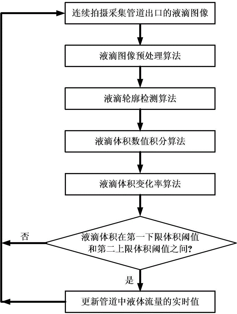
[0033] The camera or camera 3 continuously shoots and collects images of the pipeline outlet droplet 2 located at the end of the pipeline outlet section 1, and the computer or electronic computing device 4 calculates the volume change of the droplet according to the droplet image to calculate the liquid flow in the pipeline in real time.

[00...

Embodiment 2

[0088] Embodiment 2 is a multi-pipeline micro-flow detection device, such as Figure 7 As shown, the detection device is composed of a camera or a camera 3 , a computer or an electronic computing device 4 . Wherein the pipeline outlet section 1 is a pipeline outlet section array composed of a plurality of pipeline outlet sections.

[0089] Since the collected image is a droplet array, the image needs to be segmented first to obtain an image of a single droplet, and then the calculation is performed for each droplet according to the microflow detection algorithm flow in Embodiment 1.

[0090] The purpose of this embodiment is to simultaneously perform real-time, on-line, accurate, low-cost, and non-contact flow detection of liquids in multiple micro-pipes.


PUM


Abstract

A micro-flow detection method based on recognition of droplet images at a pipeline outlet comprises the steps of collecting the droplet images at the pipeline outlet through continuous shooting by a webcam or a camera; and subjecting the collected droplet images to a droplet image pretreatment algorithm, a droplet contour detection algorithm, a droplet volume numerical integration algorithm, a droplet volume change rate algorithm and the like to obtain the volume change rate of the droplets, and calculating the liquid capacity in the pipeline in real time. The micro-flow detection method based on the recognition of the droplet images at the pipeline outlet can perform real-time, on-line, accurate, low-cost and non-contact type flow detection on the liquid in a single pipeline or in a plurality of pipelines simultaneously, is particularly suitable for the detection of micro-liquid capacity in micro-pipelines with millimeter-scale, submillimeter-scale and micron-scale diameters, and can be extensively applied to micro chemical engineering devices and micro fluid systems such as a microfluidic system, a micro-electro-mechanical system, a liquid chromatograph and the like.

Description

technical field [0001] The invention relates to liquid flow detection technology, in particular to a micro-flow detection method based on image recognition of pipe outlet droplets. Background technique [0002] In recent years, the application technology of continuous flow microfluidics in chemical engineering, that is, microchemical process, has received more and more attention in the field of microscopic technology and chemical engineering. The process of micro-chemical industry can realize the continuous chemical reaction in a small volume range, so that the conversion rate and selectivity of the reaction are significantly improved, and the heat transfer coefficient and mass transfer performance are significantly enhanced compared with the conventional scale chemical process . The new process of microchemical industry can meet the requirements of industrial scale production for process intensification, realize "better" (high yield, better selectivity) and "faster" (high ...

Claims


Application Information

Patent Timeline
Patent Type & Authority Applications(China)
IPC IPC(8): G01F3/00
Inventor 卢建刚叶昕鑫
Owner ZHEJIANG UNIV
Learn More