Light-guiding plate with holes and manufacturing method thereof

A light guide plate and technology with holes, applied in the field of light guide plates, can solve the problems that the light distribution curve cannot be changed, and the light guide point is monotonous without change, achieving the effect of vivid and beautiful appearance, improving practicability and artistry, and reducing costs

Inactive Publication Date: 2013-06-12
元邦金科技研发中心(广州)有限公司
View PDF5 Cites 11 Cited by
  • Summary
  • Abstract
  • Description
  • Claims
  • Application Information

AI Technical Summary

Problems solved by technology

[0003] In order to solve the technical problem that the light guide point of the existing light guide plate is monotonous and unchanged, and the curve of the light distribution cannot be changed, the present invention proposes a light guide plate with holes that can change the light distribution curve and its manufacturing method

Method used


Image

  • Light-guiding plate with holes and manufacturing method thereof
  • Light-guiding plate with holes and manufacturing method thereof
  • Light-guiding plate with holes and manufacturing method thereof

Examples


Embodiment Construction

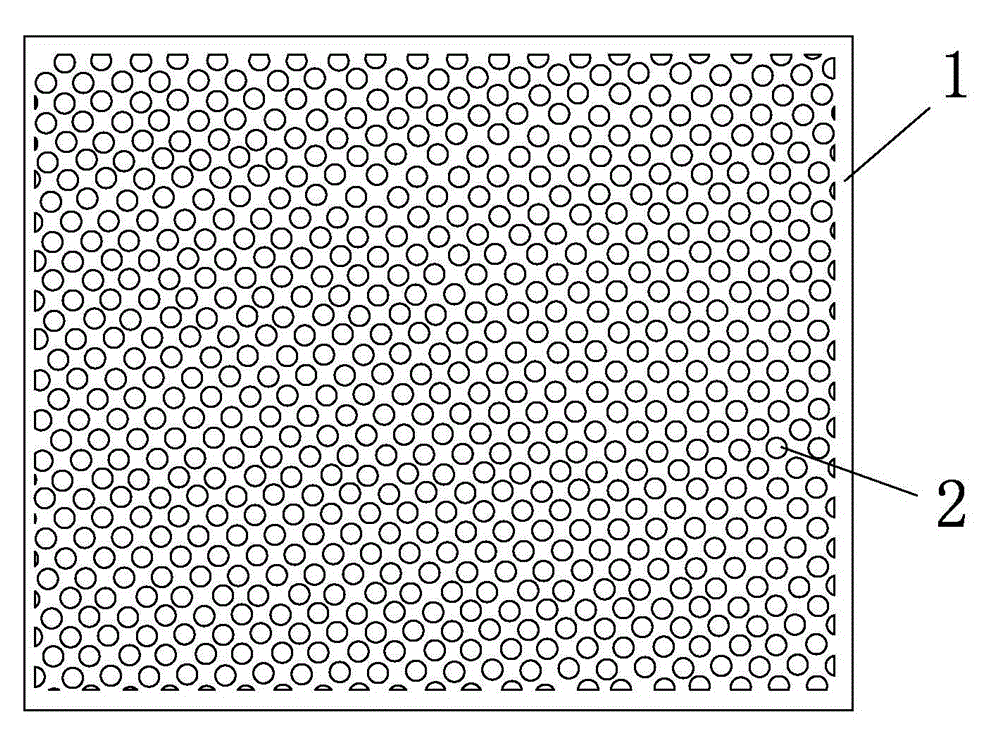
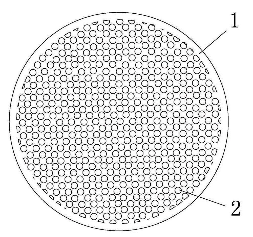
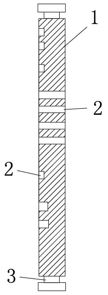
[0034] like Figure 1 to Figure 10 As shown, the light guide plate with holes proposed by the present invention includes a plate body 1 and a light source 3 disposed on the side of the plate body, and at least one side of the plate body is provided with a light guide hole 2 .

[0035] see image 3 , Figure 4 , the light guide holes 2 of the present invention can be blind holes (different depths) arranged on one or both sides of the light guide plate 1, or a mixture of blind holes and through holes, or all through holes. see Figure 5 ~ Figure 7 , said blind hole or through hole 2 can be a vertical hole or an inclined hole, or a mixed arrangement of vertical holes (90 degrees) and inclined holes (such as 45 degrees, 35 degrees, etc.). The shape of the light guide hole 2 can be a kind of circular hole, elliptical hole or polygonal hole, and can also be any mixed arrangement of vertical hole, oblique hole or polygonal hole. The aperture sizes of the light guide holes 2 may b...


PUM


Abstract

The invention discloses a light-guiding plate with holes. The light-guiding plate comprises a plate (1) and a light source (3) arranged on the side of the plate body, wherein light-guiding holes (2) are formed in at least one side surface of the plate body. The invention also discloses a manufacturing method of the light-guiding plate with holes. Various small holes are formed in the surface of the light-guiding plate. A lighting distribution curve (the lighting distribution curve of the traditional light-guiding plate is fixed) is adjusted by perforating the light-guiding plate and through the difference of perforation, the defect that the light-guiding plate needs to relay on a diffusion plate to serve as an LED (light-emitting diode) panel is overcome, and the practicability and the artistry are improved.

Description

technical field [0001] The invention relates to a light transmission device, in particular to a light guide plate suitable for various types of lighting, artistic lighting and decorative lighting, decorative materials, showcases, cabinets, display stands, etc. and a manufacturing method thereof. Background technique [0002] The design principle of the light guide plate is derived from the liquid crystal display screen of the notebook computer. The light guide plate uses fluorescent lamps, CCFL, and LED light sources to pass through the light guide point or light guide groove calculated according to the optical principle, and under the action of the reflective film (reflector) and the diffusion film, the line light source or point light source is transformed into a surface light source. In order for the light guide plate to emit light evenly, it must pass through various light guide points of different densities and sizes to ensure that the efficiency of light reflection in ...

Claims


Application Information

Patent Timeline
Patent Type & Authority Applications(China)
IPC IPC(8): G02B6/00F21V8/00F21Y101/02
CPCG02B6/0036G02B6/006G02B6/0065
Inventor 刘锡
Owner 元邦金科技研发中心(广州)有限公司
Why Eureka
Try Eureka