Broadside coupled feeding multi-band frequency broadband planar antenna

A wide-side coupling and planar antenna technology, which is applied in the connection of antennas, antenna grounding switch structures, and devices that enable antennas to work in different bands at the same time, can solve problems such as difficult miniaturization requirements, large antenna size, and difficult antenna design. Achieve the effects of easy mass production, low cost, and large capacitance adjustment range

Inactive Publication Date: 2013-06-12
SOUTHEAST UNIV
View PDF5 Cites 5 Cited by
  • Summary
  • Abstract
  • Description
  • Claims
  • Application Information

AI Technical Summary

Problems solved by technology

Low frequency means larger antenna size, more difficult to meet miniaturization requirements, and increased bandwidth makes antenna design more difficult, so th

Method used


Image

  • Broadside coupled feeding multi-band frequency broadband planar antenna
  • Broadside coupled feeding multi-band frequency broadband planar antenna
  • Broadside coupled feeding multi-band frequency broadband planar antenna

Examples


Embodiment 1

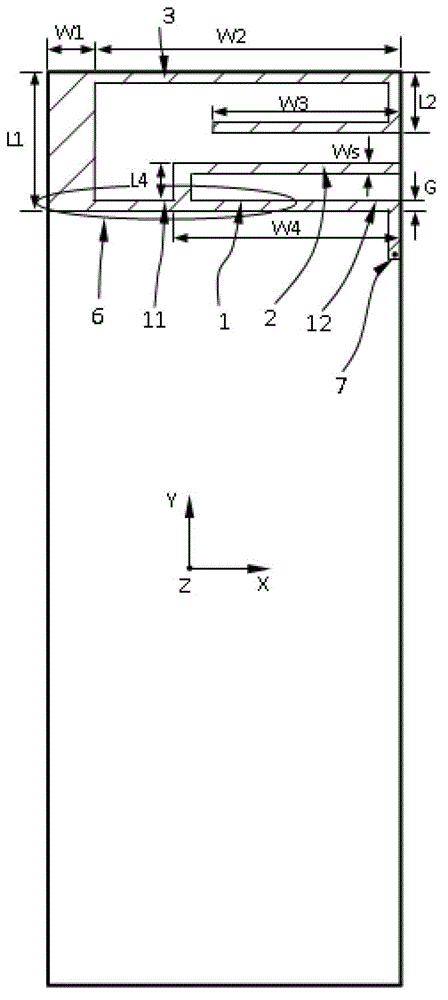
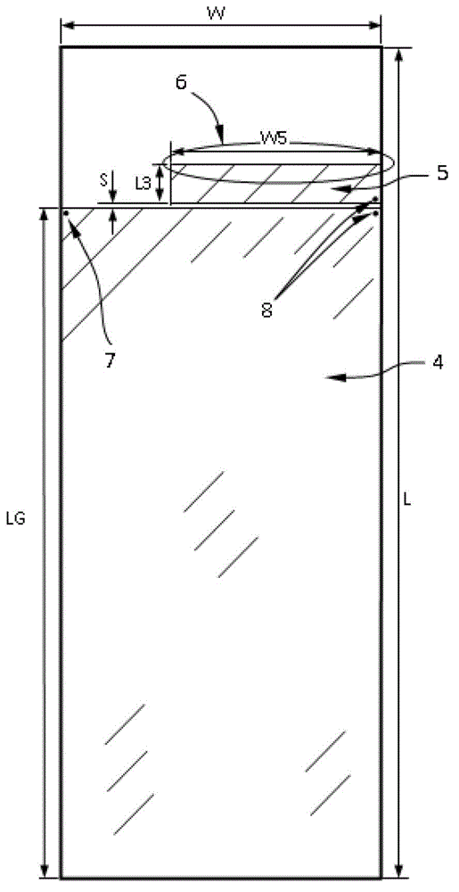
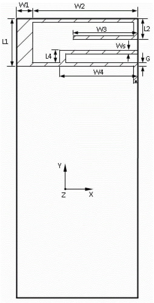
[0025] Example 1, such as figure 1 , figure 2The shown multi-band broadband planar antenna with broadside coupling and feed is on the front side of the dielectric substrate, the width of the strip 1 is Ws, and the strip 1 is arranged along the direction of the length W5 of the monopole 5 on the opposite side of the antenna, and the length is the entire dielectric substrate The width W of the width W plus the bent section connected to the metallized through hole 7, the upper edge of the strip 1 is flush with the upper edge of the reverse monopole 5, that is, the width G of the broadside coupling structure 6 is consistent with Ws, and the broadside The length of the coupling structure 6 is consistent with the length W5 of the monopole 5. After the end of the strip 1 is bent, the rest of the strip 1 is short-circuited with the ground plane 4 on the opposite side of the dielectric substrate through the metallized through hole 7 to form a short-circuit stub 12. 1 is provided with...

Embodiment 2

[0026] Example 2, such as image 3 , Figure 4 As shown, the short slots 91 are arranged symmetrically along the width W direction of the dielectric substrate on both sides of the ground plane 4 toward the center, and the long slots 92 are symmetrically arranged at the center of the substrate width direction, and are arranged along the ground plane according to a period D. Set multiple groups (7 groups in this example) in the LG direction of the length of 4, so that the curved paths cut out by the short slots 91 and the long slots 92 on the ground plane are symmetrical, and the current on the ground plane 4 runs along the short slots 91 and the long slots. The curved path flow cut out by the slot 92 greatly increases the electrical length of the current path on the ground plane 4, so that a shorter ground plane can be used to obtain the same performance as an antenna with a longer ground plane size under the same operating frequency condition , to achieve the purpose of furth...


PUM


Abstract

The invention discloses a broadside coupled feeding multi-band frequency broadband planar antenna, which comprises a medium substrate, wherein the medium substrate comprises one surface regarded as a front side and another surface which corresponds to the front side and is regarded as an opposite side, the front side of the medium substrate is provided with a metal strip in the width direction, a first bent strip and a second bent strip are connected with the metal strip, the opposite side is provided with a metal surface and a monopole, the monopole is arranged from one side to the other side in the width direction, the monopole and the metal surface are separated by a gap, the monopole is fed by a feeding port formed by two feeding points which are near one side of the medium substrate and are respectively positioned and arranged at two sides of the gap, the mutual parts of projections of the metal strip and the monopole are overlapped, and in positions beyond the region being overlapped with the projection of the monopole, the metal strip is bent at the other side opposite to the feeding port and is then in short circuit with the metal surface through the metal through hole to form a short circuit strip. The broadside coupled feeding multi-band frequency broadband planar antenna has the advantages that the structure is simple, and the integration with a radio-frequency circuit system arranged on a PCB (printed circuit board) is easy.

Description

technical field [0001] The invention relates to a multi-band broadband planar antenna, in particular to a multi-band broadband planar antenna fed by broadside coupling, in which a monopole in the form of a patch is used to simultaneously excite a coupled resonant ring and a deformed inverted F structure in a broadside coupling manner The multi-frequency antenna is used to construct a planar antenna for multi-band broadband work and a compact ground plane structure by slotting a metal surface (ground plane), which is suitable for mobile communication terminal antennas that work in multi-frequency and multi-mode. Background technique [0002] At present, more and more functions can be realized by mobile communication terminals. For example, a handheld device integrates two or more voice call service modes, and can work in different frequencies and different standard communication systems to meet the needs of users in different operations. Quotient, use requirements under diffe...

Claims


Application Information

Patent Timeline
IPC IPC(8): H01Q1/38H01Q1/50H01Q5/01H01Q5/10
Inventor 蒯振起马晨朱晓维洪伟
Owner SOUTHEAST UNIV
Why Eureka
Try Eureka