Hand-held electric blower

A blower, hand-held technology, applied in the field of air launch devices, can solve the problems of pollution, general performance and high noise

Active Publication Date: 2013-06-12
PELLENC SA
View PDF7 Cites 27 Cited by
  • Summary
  • Abstract
  • Description
  • Claims
  • Application Information

AI Technical Summary

Problems solved by technology

However, the noise remains abnormally high, and the performance remains mediocre
[0011] In conclusion, various representative documents of the prior art have disadvantages such as high energy consumption, low performance and great noise pollution

Method used


Image

  • Hand-held electric blower
  • Hand-held electric blower
  • Hand-held electric blower

Examples


Embodiment Construction

[0039] An advantageous but by no means limiting example of a blower according to the invention will now be described with reference to the accompanying drawings.

[0040] In the following description and claims, the terms "high" and "low" are used with reference to the position of the blower when in operation. These terms therefore do not have any limiting meaning.

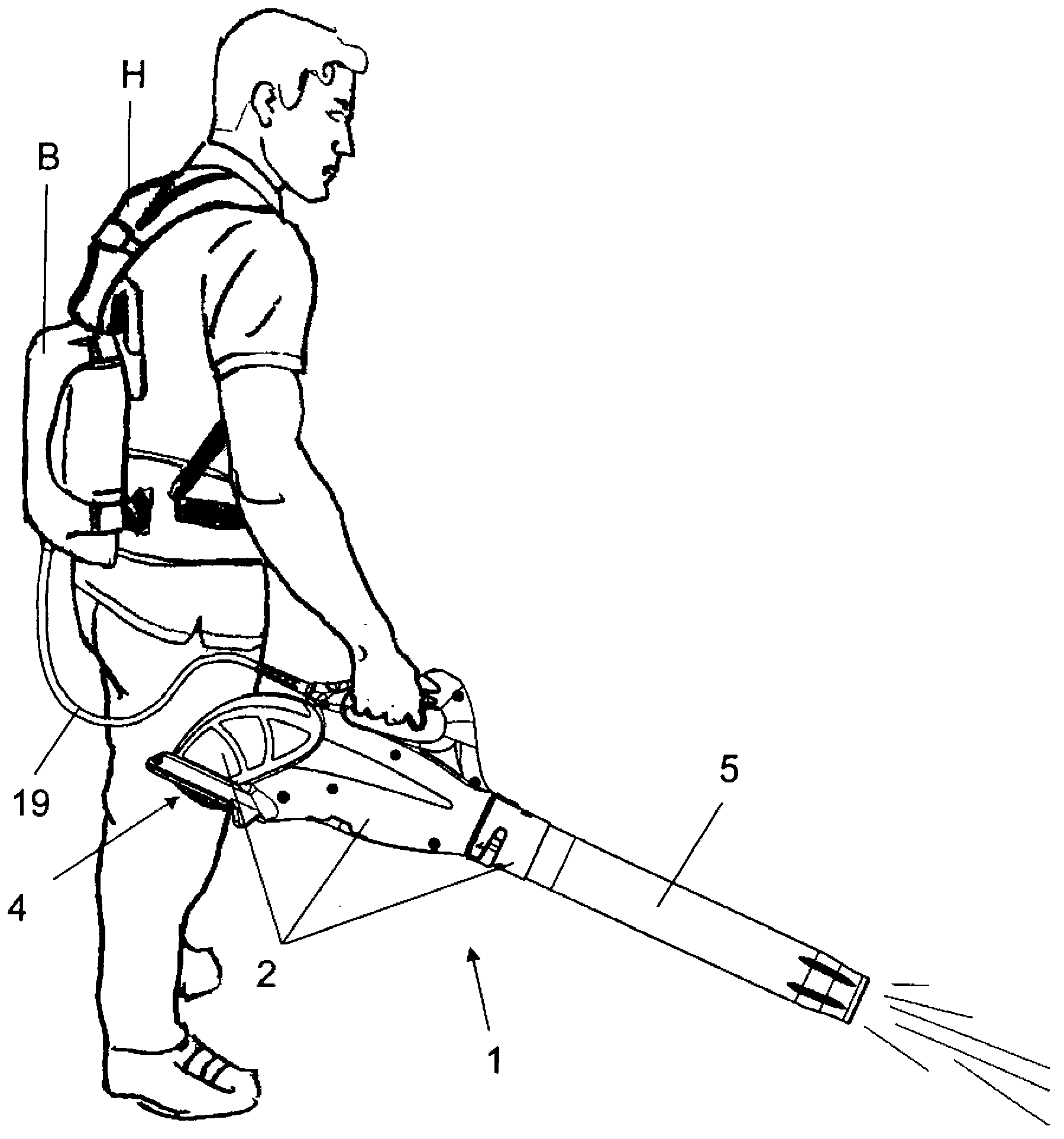
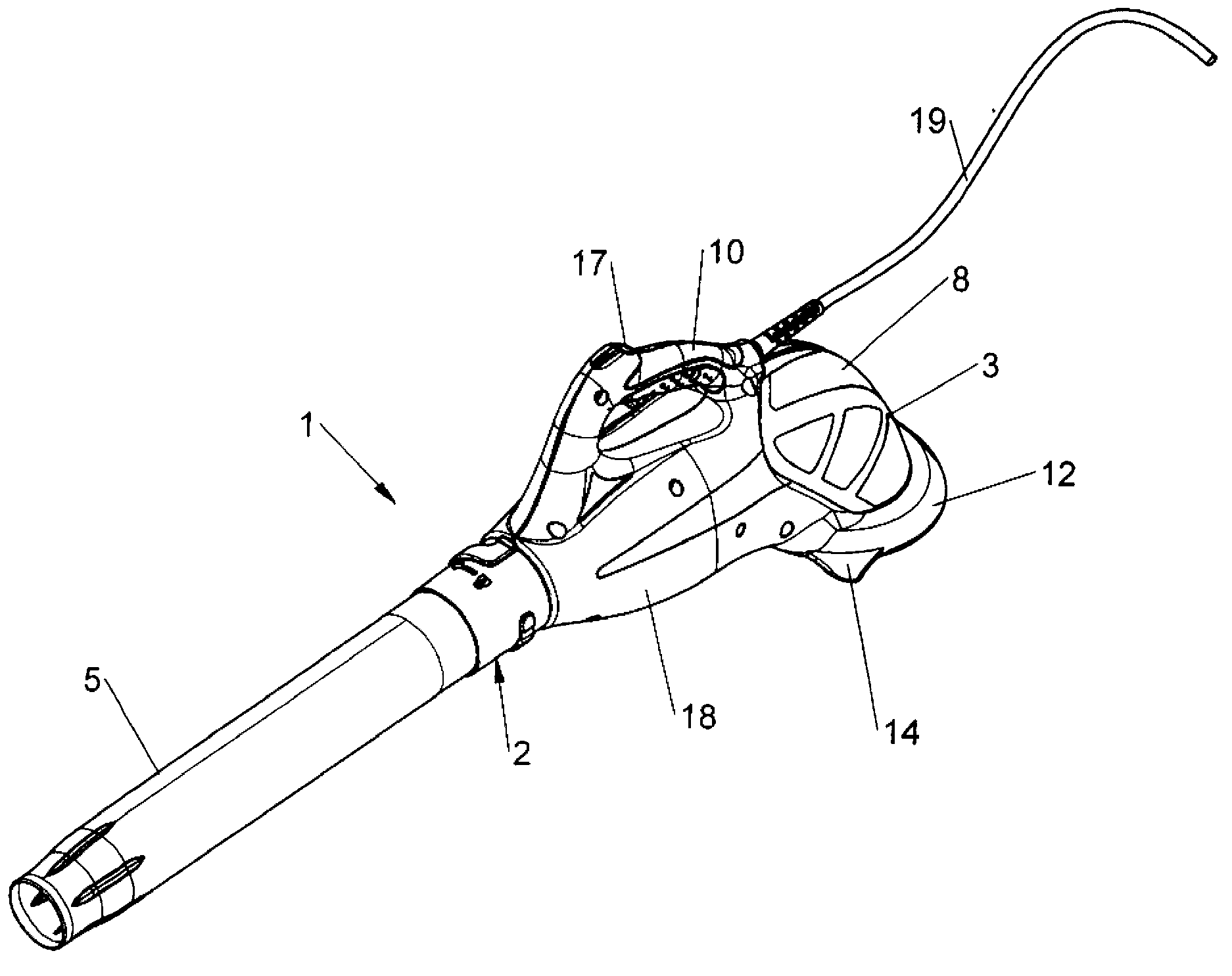
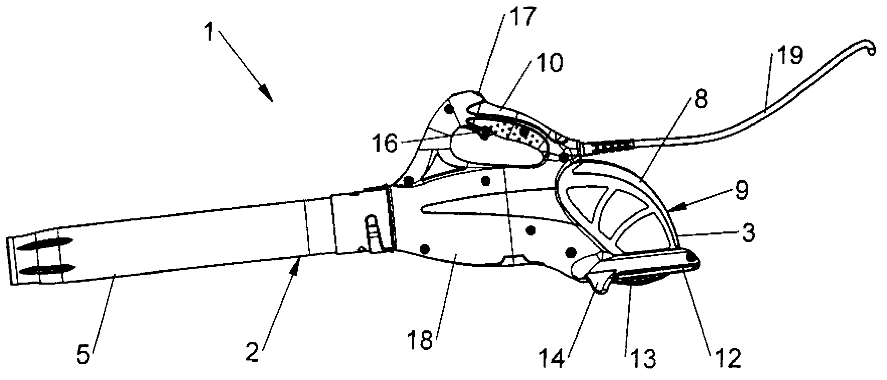
[0041] figure 2 The blower 1 shown in mainly comprises an air guide duct 2 having a proximal part or suction duct 3 provided with an air inlet 4 , a distal air outlet part or exhaust nozzle 5 and a fan 6 .

[0042] According to the invention, a fan 6 is accommodated in the middle part 7 of the air guiding duct 2 , more precisely in the suction duct 3 , and this fan 6 is of the axial flow type.

[0043] Furthermore, the blower 1 is powered by an electric motor 15 in direct contact with the axial fan 6 .

[0044] The suction duct 3 has an elbow 8 upstream of the axial fan 6, the proximal end of which elbow delim...


PUM


Abstract

The invention relates to a hand-held electric blower (1) including an air-guiding pipe (2) comprising a proximal portion or suction pipe (3) provided with an air inlet (4), a distal air outlet portion or exhaust nozzle (5), and a fan (6). According to the invention, said fan (6) is characterized in that it consists of an axial fan (6), and in that said suction pipe (3) has, upstream from the axial fan (6), an elbow (8), the proximal end of which defines the air inlet (4) and is directed downward in terms of a working position of the device, in which the operating handle (10) of the blower is positioned above said elbow.

Description

technical field [0001] The present invention relates to a hand-held (portable) electric blower. [0002] The present invention relates to the field of air launching devices for "sweeping" dry leaves or various litter that may cover large surfaces, such as lawns, public roads, outdoor car parks and the like. The results obtained with these air launching devices are similar to those obtained by using a traditional broom or rake. The invention also relates to the field of emission devices for treatment products, such as plant protective treatment products. [0003] These devices can be used for professional use as well as for domestic use. Background technique [0004] These "blowers" are extremely versatile due to their extreme ease of use, the speed at which cleaning tasks are performed and their efficient action. [0005] Such devices consist essentially of an air guide tube comprising a proximal air inlet part or suction tube, a distal air outlet part or exhaust tube, an...

Claims


Application Information

Patent Timeline
Patent Type & Authority Applications(China)
IPC IPC(8): E01H1/08A47L5/14A01G1/12
CPCA01G20/47E01H1/0809
Inventor R·佩朗
Owner PELLENC SA
Why Eureka
Try Eureka