Side channel blower, in particular a secondary air blower for an internal combustion machine

A technology of secondary air and blower, which is applied to the components of pumping devices for elastic fluids, machines/engines, mechanical equipment, etc., to achieve the effect of minimizing noise and noise emission

Active Publication Date: 2013-06-12
PIERBURG GMBH & CO KG NEUSS
View PDF7 Cites 9 Cited by
  • Summary
  • Abstract
  • Description
  • Claims
  • Application Information

AI Technical Summary

Problems solved by technology

[0009] The technical problem underlying the invention is therefore to create a side channel blower with which the housing noise occurring even when the valve is closed is significantly reduced

Method used


Image

  • Side channel blower, in particular a secondary air blower for an internal combustion machine
  • Side channel blower, in particular a secondary air blower for an internal combustion machine
  • Side channel blower, in particular a secondary air blower for an internal combustion machine

Examples


Embodiment Construction

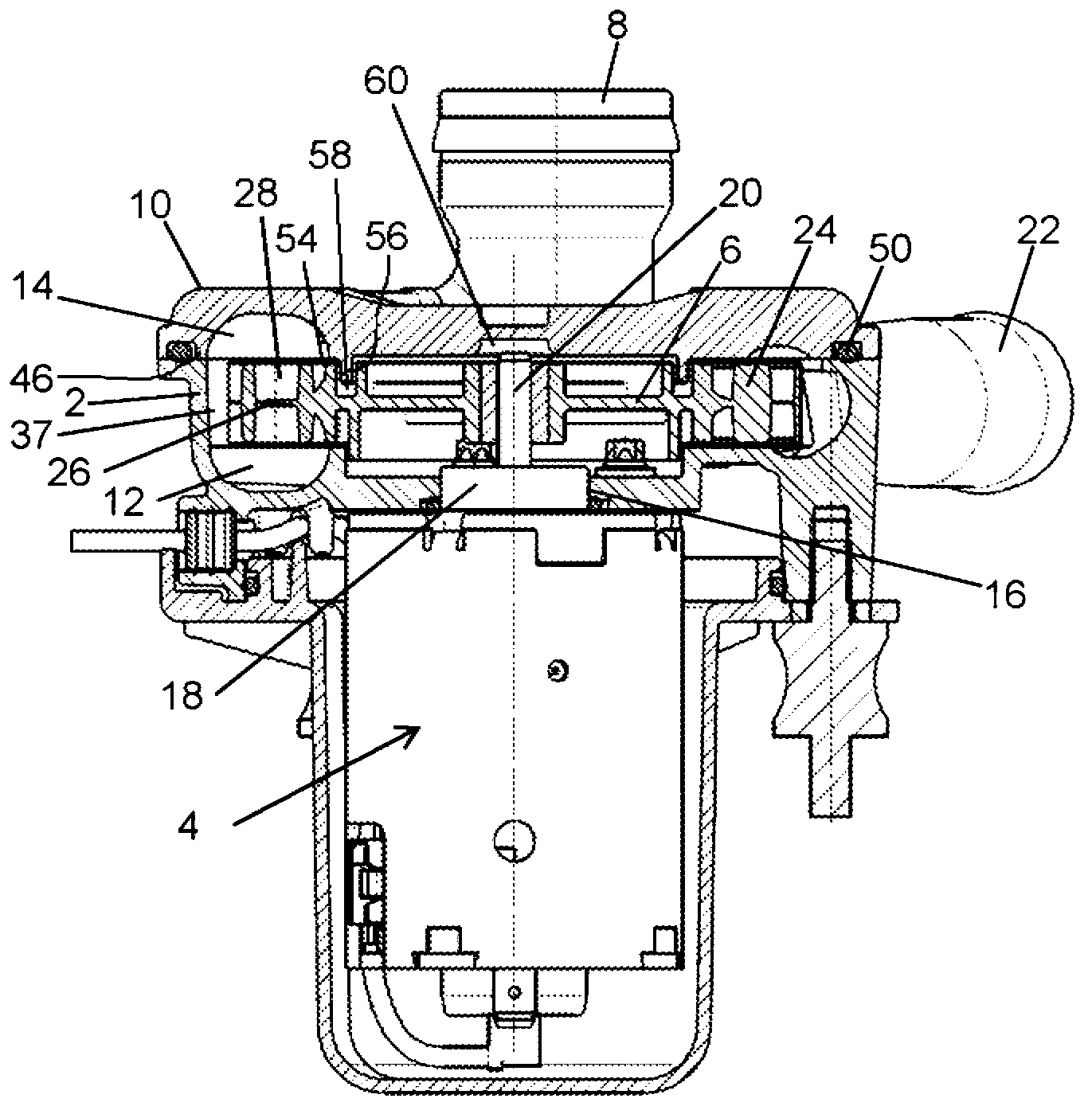
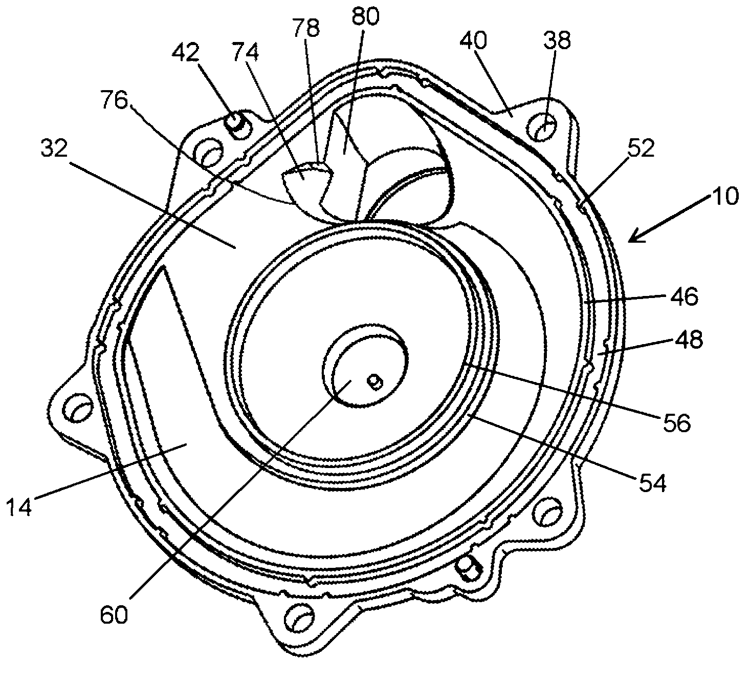
[0024] exist figure 1 The side-channel blower shown in FIG. 2 consists of a housing 2 and an impeller 6 , which is rotatably mounted in the housing 2 and driven by a drive unit 4 , for example for conveying air. Air enters the interior of the side channel blower through an axial inlet 8 formed in the housing cover 10 .

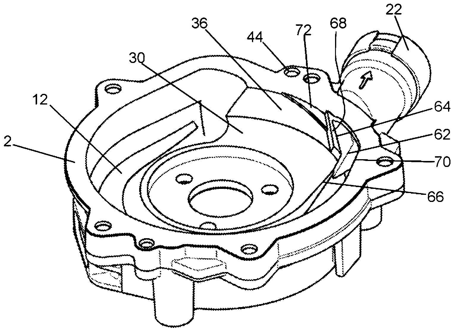
[0025] The air then flows out from the inlet 8 into two substantially annularly extending conveyor channels 12 , 14 , the first conveyor channel 12 of which is formed in the housing 2 . The bearing 18 of the drive shaft 20 of the drive unit 4 is also arranged in the central opening 16 of the drive unit 4 , on which the impeller 6 is fastened, and the second conveying channel 14 is formed in the housing cover 10 . The air exits through a tangential outlet 22 arranged in the housing 2 .

[0026] The impeller 6 is arranged between the housing cover 10 and the housing 2 and has curved conveyor blades 24 on its circumference, wherein the general direction of exte...


PUM


Abstract

Side channel blowers having devices for minimizing noise emissions are known that do not, however, sufficiently reduce noise when the control valve is closed. The invention therefore proposes a side channel blower, in which further recesses (72, 64) are formed in the interruption region (32, 34) before the inlet (8) and after the outlet (22), the smallest distance therebetween being 0.5 to 3 times the distance between two conveying blades (26). Such an embodiment achieves further noise reduction, even when the control valve is closed, without reducing the maximum flow rate.

Description

technical field [0001] The invention relates to a side channel blower, in particular a secondary air blower for an internal combustion engine, with a housing in which an essentially tangential outlet is formed, a housing cover in which an axial inlet is formed , at least one conveyor channel fluidly connecting the inlet with the outlet, an impeller rotatably supported in the housing and having conveyor blades cooperating with the at least one conveyor channel, driveable by a drive unit, and between the outlet and the outlet An interruption region between the inlets in which at least one conveyor channel is interrupted in the circumferential direction, wherein a first groove is formed on the radially delimiting wall of the interruption region behind the outlet in the direction of impeller rotation. Background technique [0002] Side channel blowers or pumps are generally known and described in numerous applications. In vehicles, the blower is used, for example, to deliver fu...

Claims


Application Information

Patent Timeline
Patent Type & Authority Applications(China)
IPC IPC(8): F04D23/00F04D29/66
CPCF04D23/008F04D29/667F04D29/161F01D25/24
Inventor B.赫尔曼R.彼得斯
Owner PIERBURG GMBH & CO KG NEUSS
Why Eureka
Try Eureka