Wideband dual-polarized radiation element and antenna of same

A radiation unit and broadband antenna technology, which is applied to antenna unit combinations with different polarization directions, radiation element structure forms, antennas, etc., can solve problems such as low electrical performance, reduced electrical performance, and poor pattern, and achieve good radiation performance , good performance, extended length effect

Active Publication Date: 2013-06-12
TONGYU COMM INC
View PDF4 Cites 11 Cited by
  • Summary
  • Abstract
  • Description
  • Claims
  • Application Information

AI Technical Summary

Problems solved by technology

[0005] (1) Linear dipoles create a huge dipole matrix; at the same time it degrades the performance of high frequency radiating elements located between low frequency radiating elements
In addition, coupling between low frequency radiating elements degrades its electrical performance
[0006] (2) The structure of the balancer is linear, so that the distance between the low-frequency radiation unit and the high-frequency radiation unit is relatively close, and the impedance and pattern performance of the high-frequency radiation unit are affected by the low-frequency radiation unit, resulting in lower electrical performance and poor performance. direction map
[0007] Although the design of the patent CN201134512Y has been improved compared with the US patent US6333720B1, it still has the following disadvantages: (1) The high-frequency radiation unit is embedded in the low-frequency radiation unit to realize the multi-frequency antenna design, and the balance between the high-frequency radiation unit and the low-frequency radiation unit close to the device, the VSWR and radiation performance of the high-frequency radiation unit will be greatly affected
(2) Although the design converges the radiation aperture, all the dipoles at one end are bent downward, which increases the adverse effect on the high-frequency radiation unit
(3) The patent widens the working bandwidth by dipoles of different thicknesses, especially at the ends, which increases manufacturing difficulties and reduces the reliability of the radiation unit

Method used


Image

  • Wideband dual-polarized radiation element and antenna of same
  • Wideband dual-polarized radiation element and antenna of same
  • Wideband dual-polarized radiation element and antenna of same

Examples


Embodiment Construction

[0031] It should be noted that, in the case of no conflict, the embodiments in the present application and the features in the embodiments can be combined with each other. The present invention will be further described in detail below in conjunction with the drawings and specific embodiments.

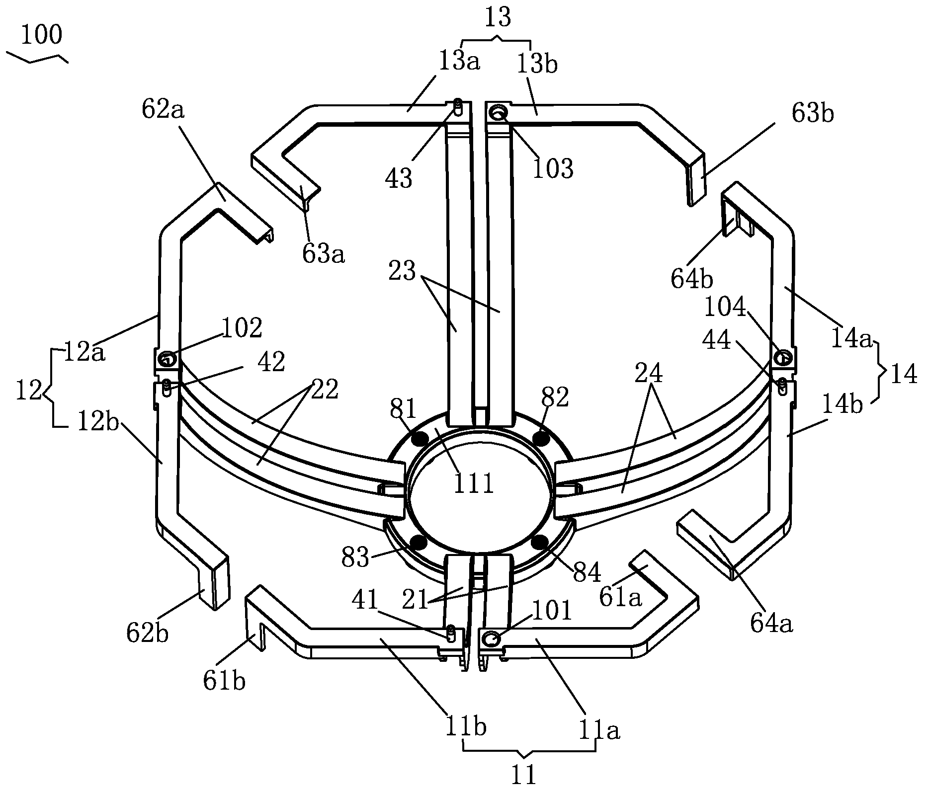
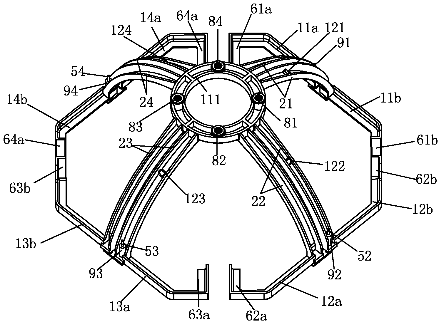
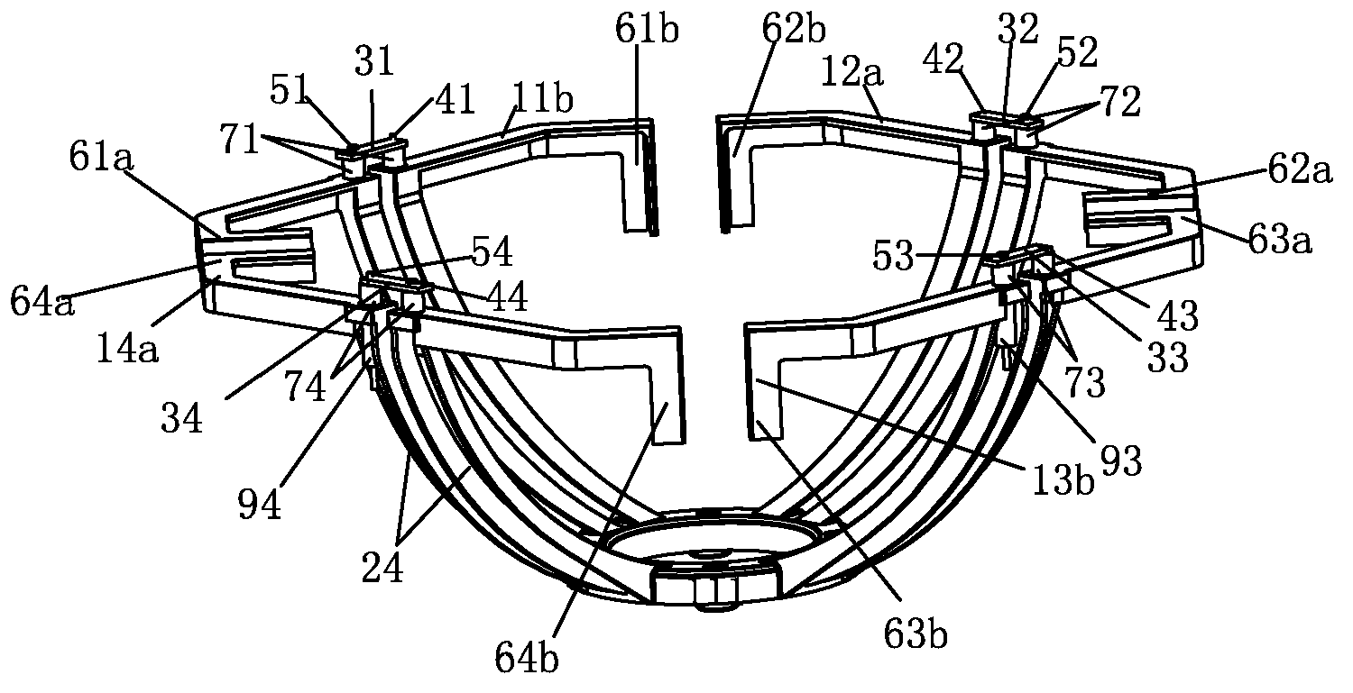
[0032] refer to figure 1 , figure 2 and image 3 , a broadband high-performance dual-polarized radiating unit 100, including orthogonally polarized dipoles, a feeder for balanced feeding each dipole, and a ring connector 111 for fixing the bottom of the balancer . The radiating unit 100 includes two pairs of octagonal cross-polarized dipoles 11 , 12 , 13 , 14 mounted on top of balancers 21 , 22 , 23 , 24 . The radiation unit 100 is an integrated die-casting unit.

[0033] In a preferred embodiment, the dipoles 11, 12, 13, 14 have the same structure, and each dipole includes a pair of unit arms 11a and 11b, 12a and 12b, 13a and 13b, 14a and 14b respectively. One end of each pair o...


PUM


Abstract

A wideband dual-polarized radiation element includes two pairs of cross polarized dipoles (11,12,13,14) and baluns (21,22,23,24), which correspondingly feed current to each dipole in balanced manner. Each dipole includes a pair of unit arms (11a and 11b, 12a and 12b, 13a and 13b, 14a and 14b) aligned on top of the corresponding balun. One end of each unit arm is connected on top of the balun, and the other end of one unit arm is bending inwards to form inward loaded line (61a, 62a, 63a, 64a), and the other unit arm is bending downwards to form downward loaded line(61b, 62b, 63b, 64b). An antenna (10) includes a metal reflector (20) and at least one wideband dual polarized radiation element, which has excellent radiation and polarization performance.

Description

technical field [0001] The invention relates to the field of mobile communication base station antennas, in particular to a broadband high-performance dual-polarized radiation unit and a broadband antenna. Background technique [0002] Currently, under the coexistence of 2G and 3G networks, the demand for multi-band antennas compatible with 2G and 3G networks continues to grow. With the development of communication technology, higher and higher requirements are put forward for the performance index of the multi-frequency antenna. [0003] Based on the above development trend, two pairs of cross-polarized dipoles in a square or circular design are commonly used in the market at present. For example, US Pat. No. 6,333,720 B1 discloses an antenna. The low-frequency radiation unit described in this patent includes two pairs of cross-polarized dipoles arranged in a dipole matrix. The performance of multi-frequency antennas is achieved by embedding high-frequency radiating eleme...

Claims


Application Information

Patent Timeline
Patent Type & Authority Applications(China)
IPC IPC(8): H01Q1/36H01Q5/01H01Q19/10H01Q21/26H01Q5/10
CPCH01Q1/246H01Q9/26H01Q19/106H01Q21/24H01Q21/30H01Q9/16
Inventor 洪何知石磊方铁勇伍裕江高卓锋刘木林叶海欧
Owner TONGYU COMM INC
Why Eureka
Try Eureka