
Patsnap Eureka
For R&D, Patsnap Eureka makes reading and utilizing patents & technical documents easy.
Patsnap Eureka AIR
Designed for self-driven R&D workflows. Generate viable solutions, solve complex R&D challenges, empower your innovation with AI.

Patsnap Eureka Materials
Designed for material experts only. Revolutionize your material R&D, from search, analyze, to developing new materials.

TechResearch
Generate reliable direction feasibility study reports for your R&D in just a few steps.

TechSeek
Discover and master advanced knowledge NOW. Basics, ideas, possibilities, all at once.

TechMind
As an expert in R&D Theories, TechMind can generates customized viable solutions instantly.

TechRisk
Analyze your overall solution with one click, know your potential R&D risks in advance.

TechMonitor
Get weekly tech updates, stay abreast of the latest tech innovations and key insights.
Connecting rod chamfering device
A chamfering device and connecting rod technology, which is applied in the field of connecting rod chamfering devices, can solve the problems of large floor area of lathes, high equipment use cost, complicated connecting rod chamfering process, etc., and achieve small footprint and safe use , the effect of simple structure
- Summary
- Abstract
- Description
- Claims
- Application Information
AI Technical Summary
Problems solved by technology
Method used
Image

Examples
Embodiment Construction
[0008] The present invention will be further described below in conjunction with accompanying drawing:
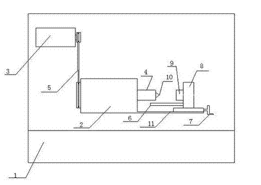
[0009] Such as figure 1 As shown, the present invention is a connecting rod chamfering device, which is provided with a workbench, a machine tool body, a motor, a main shaft, a conveyor belt, a limit screw, a handle, a clamp, a connecting rod, a chamfering knife, and a sliding guide rail, and is characterized in that: The workbench 1 is equipped with the main body of the machine tool 2 and the motor 3, the motor 3 is connected with the main shaft 4 through the conveyor belt 5, the chamfering knife 10 is mounted on the front end of the main shaft 4, the clamp 8 is clamped on the sliding guide rail 11 of the main body 2 of the machine tool, and the handle 7 is connected with the main shaft 4. The clamps 8 are connected, the bottom end of the clamps is equipped with a limit screw 6, and the connecting rod 9 is mounted on the clamps 8.
[0010] When the present invention ...
PUM
 Abstract
Description
Claims
Application Information
 - R&D Engineer
- R&D Manager
- IP Professional
- Industry Leading Data Capabilities
- Powerful AI technology
- Patent DNA Extraction
Browse by: Latest US Patents, China's latest patents, Technical Efficacy Thesaurus, Application Domain, Technology Topic, Popular Technical Reports.
© 2024 PatSnap. All rights reserved.Legal|Privacy policy|Modern Slavery Act Transparency Statement|Sitemap|About US| Contact US: help@patsnap.com