Single rotor minitype turbofan engine adopting axial flow oblique flow serial composite compressing system

A turbofan engine and compound compression technology, applied in the direction of machine/engine, mechanical equipment, non-variable-capacity pump, etc., can solve the problem that the fan cannot improve the boost ratio of the compression system, the fan does not match the core engine, and the lengthened wheel Disk axial length and other issues, to achieve the effect of large thrust, low power, and reduced axial length

Active Publication Date: 2013-06-19
南京凌日星能源科技有限公司
View PDF5 Cites 21 Cited by
  • Summary
  • Abstract
  • Description
  • Claims
  • Application Information

AI Technical Summary

Problems solved by technology

[0003] These structural forms provide possible development directions for micro turbofan engines, but they all have their own shortcomings: 1) The front fan dual-rotor concentric shafting scheme is the form adopted by existing large engines, and its miniaturization design is in structural design, There are many technical difficulties in installation and commissioning, bearings, lubrication, and engine starting; 2) In the rear fan scheme, the integral structural design of the low-pressure turbine and fan and the sealing problems of the cold and hot air flow are quite large in the size range of micro-miniature engines. Difficult, in addition, the fan can not play the role of increasing the boost ratio of the compression system; 3) The common single-rotor turbofan engine scheme can avoid the concentric shafting problem and complicated flow channel structure of the dual-rotor turbofan engine, but in practical applications , the single-rotor solution also has problems such as the mismatch between the fan and the core machine, the Mach number of the fan blade tip is too high, and the single-stage turbine is overloaded.
However, its inner channel is essentially a single-stage centrifugal compressor, and the supercharging ratio of the inner channel is limited to the range that can be achieved by a single-stage centrifugal compressor; A large total pressure loss is generated; in addition, the axial flow compression section extended forward needs to lengthen the axial length of the wheel, resulting in a large increase in the weight of the wheel

Method used


Image

  • Single rotor minitype turbofan engine adopting axial flow oblique flow serial composite compressing system
  • Single rotor minitype turbofan engine adopting axial flow oblique flow serial composite compressing system
  • Single rotor minitype turbofan engine adopting axial flow oblique flow serial composite compressing system

Examples


specific Embodiment approach

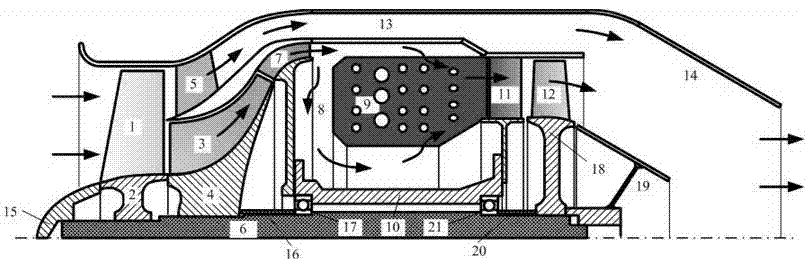
[0023] Control attached figure 1 , the present invention proposes a single-rotor micro turbofan engine with an axial-flow mixed-flow tandem compound compression system, and the left side of the figure is the engine inlet. After the airflow enters, it passes through an axial flow fan 1, which is an integral wheel structure, and 2 is a fan wheel, whose rim diameter is equivalent to the diameter of the oblique flow compressor impeller 3 directly connected to the rear, so as to ensure that the two have roughly the same rotation The linear speed of the rim makes both of them have better compressed airflow capability under the condition of strength permitting. After the airflow is pressurized by the axial flow fan, the airflow located in the smaller radius part enters the oblique flow compressor rotor 3 to continue the pressurization. The rotor of the diagonal flow compressor is also an integral disc structure, and 4 is the rotor disc of the diagonal flow compressor. After the axi...

Embodiment

[0025] For a certain existing micro-turbojet engine, according to the method proposed by the present invention, the modified design is carried out. The flow rate of the prototype is 0.9kg / s, the total pressure ratio is 4.0, and the temperature before the turbine is 1200K. At an altitude of 3000m and a flight Mach number of 0.6, through performance analysis: the thrust is 37 DaN, and the fuel consumption rate is 1.590kg / (DaN·h). After the retrofit design, three main design parameters of the tandem axial fan diagonal flow compressor micro-turbofan engine were obtained: internal total pressure ratio 4.5, external bypass total pressure ratio 1.6, and bypass ratio 1.0. According to the calculation and analysis of the overall performance, at an altitude of 3000m, under the flight Mach number of 0.6, the net thrust is 48 DaN, the fuel consumption rate is 1.378kg / (DaN h), the net thrust is 29.7% higher than that of the corresponding turbojet engine, and the fuel consumption rate is red...


PUM


Abstract

The invention provides a single rotor minitype turbofan engine adopting an axial flow oblique flow serial composite compressing system. The structure of the single rotor minitype turbofan engine adopting the axial flow oblique flow serial composite compressing system is that airflow of an outer duct of a turbofan engine and the airflow which enters into a combustor of an inner duct are both supplied by the axial flow oblique flow serial composite compressing system, the axial flow oblique flow serial composite compressing system adopts a combination of both an axial flow fan rotor and an oblique flow compressor rotor, and provides pressure boosting airflow for both the inner duct and the outer duct. The serial axial flow fan rotor is relative to the portion of the inner duct, and directly forms an oblique flow compressor impeller to a serial blade lattice form; a row of stator impellers is arranged on the axial flow fan rotor corresponding to the portion of the outer duct, the air flow is adjusted to the rear direction of the meridian plane through rectification deceleration, and flows into a turbofan engine outer duct bypass along the outer surface of an intermediary cartridge receiver. The single rotor minitype turbofan engine adopting the axial flow oblique flow serial composite compressing system has the advantages of being capable of realizing to provide the pressure boosting airflow for the inner duct and the outer duct by the needs of the turbofan engine, lowering an oil consumption rate of the engine, improving windward side thrust of each unit of the engine, and effectively improving voyage and enhancing load when the single rotor minitype turbofan engine adopting the axial flow oblique flow serial composite compressing system is applied in carriers of unmanned planes, loitering munitions, and the like.

Description

technical field [0001] The invention relates to a single-rotor miniature turbofan engine adopting an axial-flow oblique-flow tandem compound compression system, having a novel structure and a corresponding design method. It can be used for tiny turbofan engines with a thrust of hundreds of DaN or less. It specifically relates to the design of the compression system of the turbofan engine, which adopts the axial flow fan rotor impeller and the oblique flow compressor rotor impeller arranged in series as a composite compression system rotor, and there is no stator impeller between them. The composite compression system rotor can effectively increase the pressure ratio of the inner duct and provide pressurized air flow for the outer duct. Compared with the micro turbojet engine, the thrust of the micro turbofan engine is significantly increased and the fuel consumption rate is significantly reduced under the condition of only a small modification of the structure; thus, it can m...

Claims


Application Information

Patent Timeline
Patent Type & Authority Applications(China)
IPC IPC(8): F02K3/00F04D25/16
Inventor 黄国平陆惟煜傅鑫陈杰夏晨
Owner 南京凌日星能源科技有限公司
Why Eureka
Try Eureka