
High-altitude two-stage turbocharger cooling system and control method thereof

A turbocharger and cooling system technology, applied in the direction of machines/engines, internal combustion piston engines, mechanical equipment, etc., can solve the problems of large resistance loss, knocking, and inaccessibility

Active Publication Date: 2018-06-01
INST OF ENGINEERING THERMOPHYSICS - CHINESE ACAD OF SCI
View PDF9 Cites 2 Cited by
  • Summary
  • Abstract
  • Description
  • Claims
  • Application Information

AI Technical Summary

Problems solved by technology

Although this cooling system has a simple structure and is easy to adjust and control, it cannot give full play to the advantages of the two cooling methods.
On the one hand, although the water-air cooling is short and the pressure loss is small, it is beneficial to improve the response speed of the engine, but it cannot take advantage of the low temperature of the ambient air (-60°C) for interstage cooling at high altitudes, and cannot obtain The lower interstage air temperature limits the increase of the boost ratio of the rear stage and causes problems such as excessive engine intake temperature
On the other hand, although air-to-air cooling can take advantage of the low-temperature advantage of high-altitude ambient air, the intake pipe is long and the resistance loss is also large, especially in low-altitude ground take-off conditions, the ambient air is no longer significant compared to the cooling water. The temperature advantage, and the engine's low windward speed will lead to insufficient cooling capacity of the cooling air flow, and the engine intake temperature is too high, which will cause problems such as insufficient take-off power or knocking

Method used


Image

  • High-altitude two-stage turbocharger cooling system and control method thereof
  • High-altitude two-stage turbocharger cooling system and control method thereof
  • High-altitude two-stage turbocharger cooling system and control method thereof

Examples


Embodiment Construction

[0053] In order to make the object, technical solution and advantages of the present invention clearer, the present invention will be further described in detail below with reference to the accompanying drawings and examples. It should be noted that the following descriptions are only preferred embodiments of the present invention, and therefore do not limit the protection scope of the present invention.

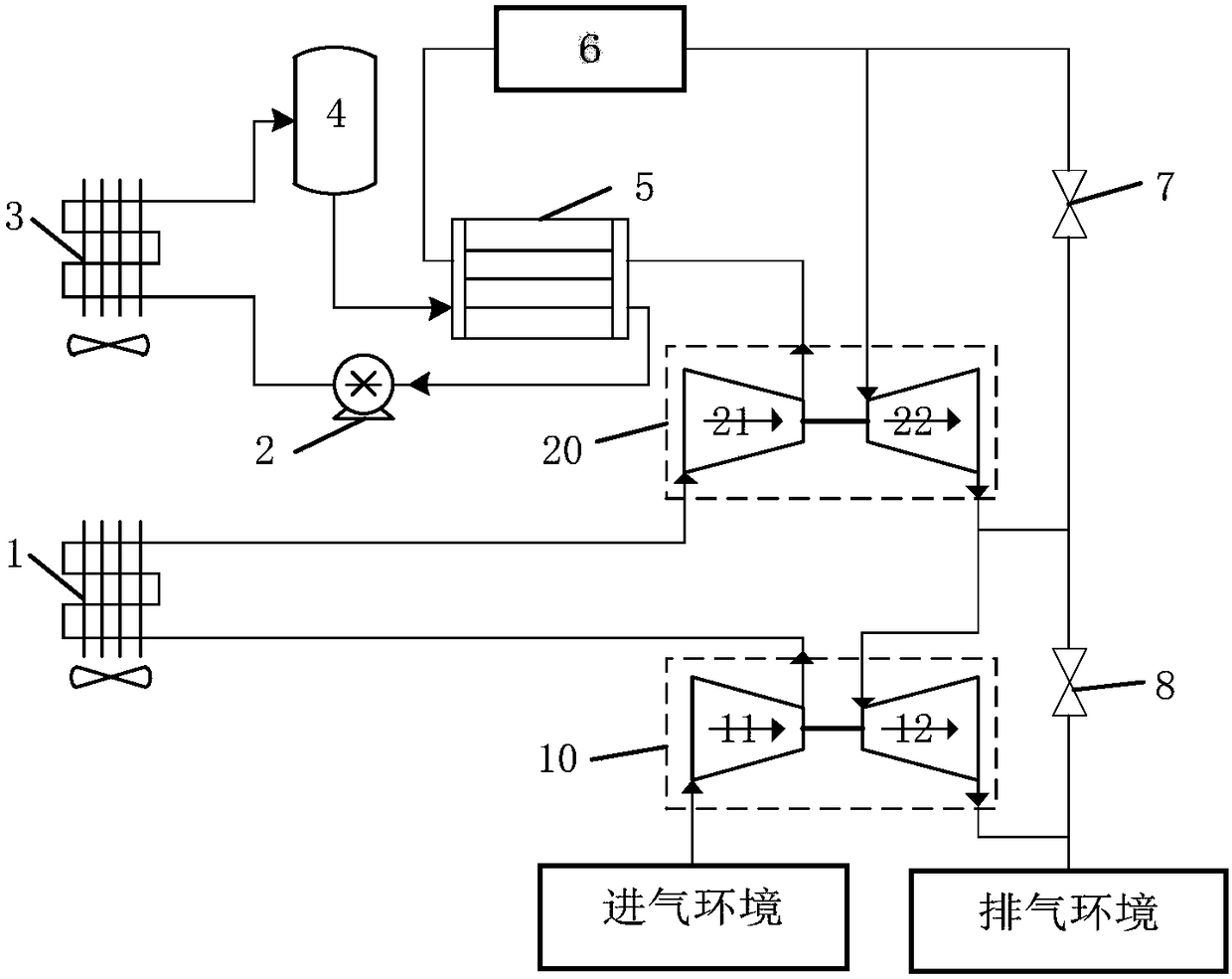
[0054] The charge air cooling system described in this embodiment is suitable for a two-stage turbocharger in a high-altitude environment, and its composition and control method will be described below with reference to the accompanying drawings.

[0055] as attached figure 1 As shown, the high-altitude two-stage turbocharger cooling system of the present invention includes a first-stage turbocharger 10, a second-stage turbocharger 20, an engine cylinder 6, an interstage air-to-air cooler 1, a supercharging Rear water-air cooler 5, circulating cooling liquid tank 4, circula...


PUM


Abstract

The invention discloses a two-stage turbocharger under a high-altitude environment, and provides a high-altitude two-stage turbocharger cooling system and a control method thereof. An air-air and water-air compound cooling system is adopted; the compound cooling system has the following main advantages: interstage air-air cooling uses advantages of a high-altitude low-temperature environment to supercharged air cooling, so that the pressure ratio of a high-pressure-stage air compressor is effectively increased, the total supercharging ratio of two stages of superchargers is increased on the basis of guaranteeing reasonable engine intake temperature, and the practical rising limit of an engine is improved; through application of water-air cooling after supercharging, layout of an intercooler on the engine is convenient, the length of an intake pipe is shortened, and the dynamic response speed of a supercharger and the engine is improved; and aiming at the compound cooling system, corresponding variable working condition adjusting control rules are given according to a heat exchanger efficiency energy-heat transfer unit number method, so that respective advantages of air-air coolingand water-air cooling under such working conditions as ground takeoff and high-altitude cruising flight are fully exerted. The high-altitude two-stage turbocharger cooling system can be used for scheme design of a two-stage turbocharging system under high-altitude environment and research of variable working condition control rules.

Description

technical field [0001] The invention relates to a turbocharger cooling system and a control method thereof, in particular to a high-altitude two-stage turbocharger cooling system and a control method thereof, belonging to the technical field of turbochargers. Background technique [0002] The turbocharger can effectively improve the volumetric efficiency of the engine and increase the power per liter of the engine, especially to maintain the intake pressure and density of the engine when the engine is working at a higher altitude, thereby ensuring power recovery. As the boost pressure increases, the intake air temperature increases, which, for a gasoline engine, increases the tendency of the engine to knock and the emission of nitrogen oxides. At the same time, as the temperature of the entire working cycle of the engine increases, the exhaust temperature increases, which leads to an increase in the heat load of the main components of the engine such as the cylinder head, pi...

Claims


Application Information

Patent Timeline
IPC IPC(8): F02B29/04
CPCF02B29/0412F02B29/0431F02B29/0437F02B29/0456F02B29/0462F02B29/0493Y02T10/12
Inventor 赵庆军孙小磊邓爱明赵巍张锴
Owner INST OF ENGINEERING THERMOPHYSICS - CHINESE ACAD OF SCI
Learn More