
A gas booster system without gas consumption

A technology of gas pressurization and gas consumption, which is applied in the direction of liquid variable displacement machinery, piston pumps, pump components, etc., can solve the problems of large energy loss, low efficiency, and inability to realize large flow gas boosting, etc., and achieves a wide range of applications , high efficiency and remarkable energy saving effect

Active Publication Date: 2019-07-23
乐清市乐翔电气有限公司
View PDF5 Cites 0 Cited by
  • Summary
  • Abstract
  • Description
  • Claims
  • Application Information

AI Technical Summary

Problems solved by technology

[0002] Existing gas booster pumps or valves use compressed air to drive a large-area piston end to produce high-pressure gas output from a small-area piston end. During the boosting process, a large amount of gas will be consumed, and the energy loss will be large. Due to the limitation of the flow rate , unable to realize the pressurization of large flow gas, the efficiency is very low

Method used


Image

  • A gas booster system without gas consumption
  • A gas booster system without gas consumption
  • A gas booster system without gas consumption

Examples


Embodiment Construction

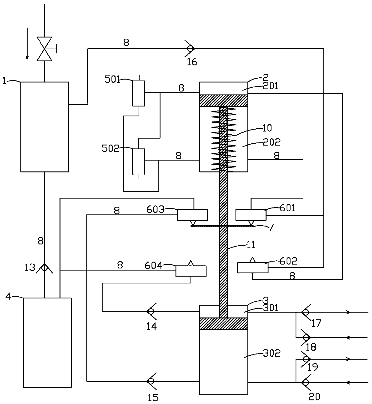
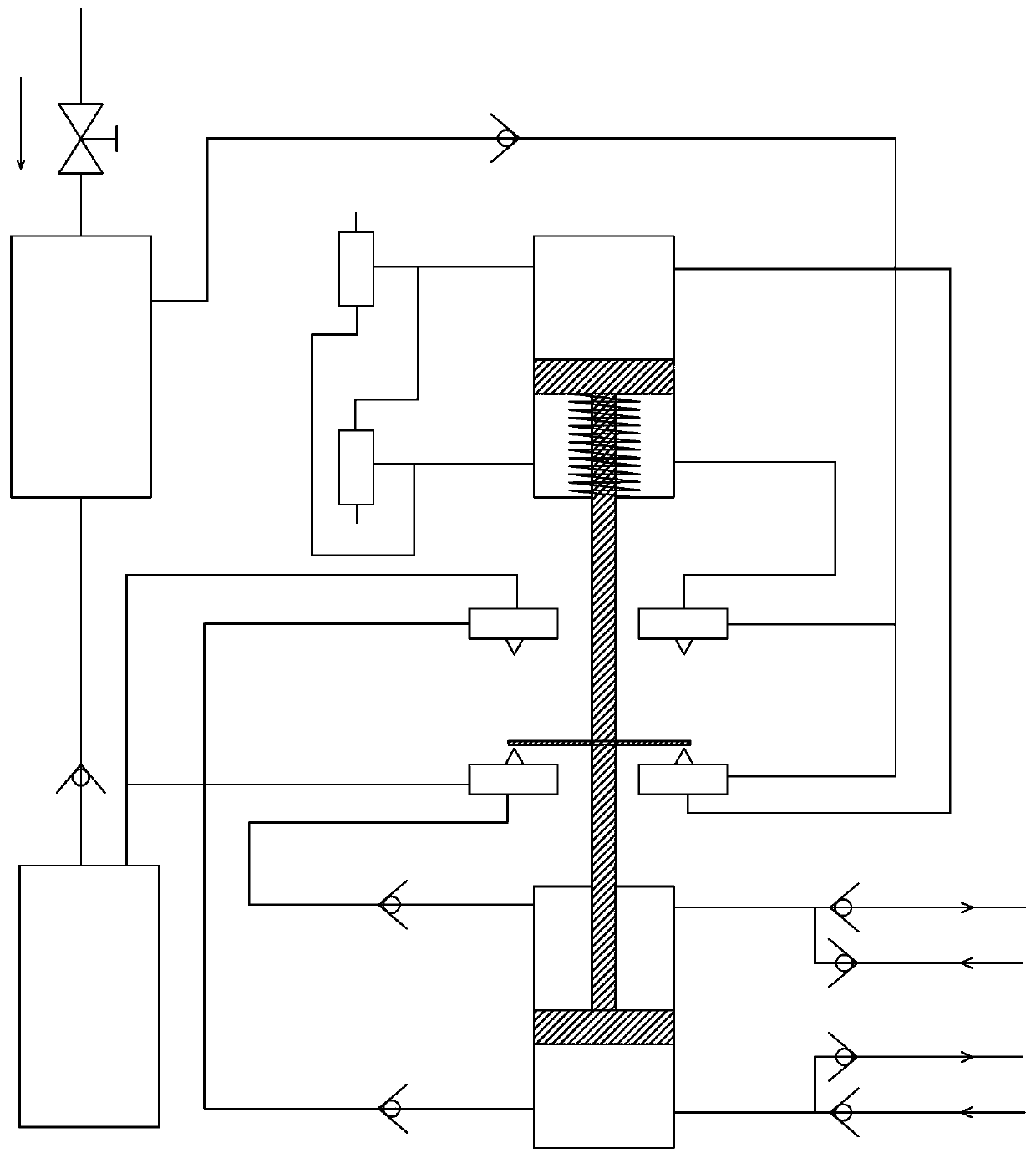
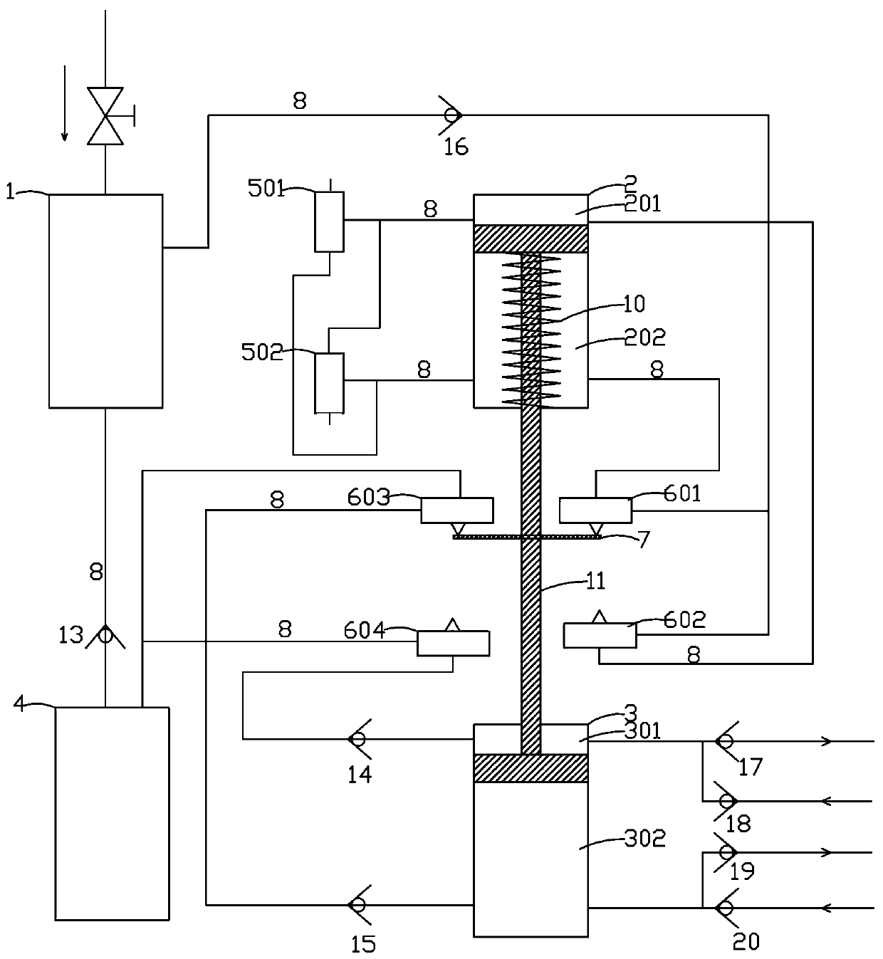
[0021] Such as Figures 1 to 2 As shown, the non-gas consumption gas pressurization system of the present invention is mainly composed of a vacuum generator 1, a vacuum cylinder 2, a piston type compression cylinder 3, a buffer gas tank 4, a vacuum valve, a trigger valve, a trigger 7 and a gas pipe 8. The vacuum generator 1 is connected to the upper vacuum chamber 201 of the vacuum cylinder 2 through the air pipe 8 one way, and the other way is connected to the lower vacuum chamber 202 of the vacuum cylinder 2, and a return spring 10 is arranged in the lower vacuum chamber 202 of the vacuum cylinder 2 . In the above, the upper vacuum chamber 201, that is, the vacuum cylinder 2, corresponds to the cavity above the piston, and the lower vacuum chamber 202, that is, the vacuum cylinder 2, corresponds to the cavity below the piston. The vacuum generator is a vacuum component that uses a positive pressure gas source to generate negative pressure. The vacuum generator is widely used...


PUM


Abstract

The invention discloses a gas consumption free gas supercharging method. According to the technical scheme, a vacuum gas cylinder and a piston type compression gas cylinder are included and share a piston rod. Pistons are arranged at the two ends of the piston rod. The method is characterized by comprising the following steps that (1) firstly the piston in the vacuum gas cylinder is pushed towardsan upper vacuum cavity through a return spring; (2) a lower vacuum cavity of the vacuum gas cylinder is vacuumized, and meanwhile a lower compression cavity of the piston type compression gas cylinder is inflated with air; (3) air enters the upper vacuum cavity of the vacuum gas cylinder, the piston in the vacuum gas cylinder overcomes resistance to be fast pushed towards the lower vacuum cavity,and therefore the piston rod drives the piston in the piston type compression gas cylinder to be fast pushed towards the lower compression cavity, and gas in the lower compression cavity of the piston type compression gas cylinder is fast exhausted; (4) the upper vacuum cavity of the vacuum gas cylinder is vacuumized, and meanwhile an upper compression cavity of the piston type compression gas cylinder is inflated with air; (5) air enters the lower vacuum cavity of the vacuum gas cylinder, the piston in the vacuum gas cylinder overcomes resistance to be fast pushed towards the upper vacuum cavity, and therefore the piston rod drives the piston in the piston type compression gas cylinder to be fast pushed towards the upper compression cavity, and gas in the upper compression cavity of thepiston type compression gas cylinder is fast exhausted; and (6) the step (2), the step (3), the step (4) and the step (5) are executed in cycles, and the piston does reciprocating motion.

Description

technical field [0001] The invention relates to a gas pressure boosting system without gas consumption. Background technique [0002] Existing gas booster pumps or valves use compressed air to drive a large-area piston end to produce high-pressure gas output from a small-area piston end. During the boosting process, a large amount of gas will be consumed, and the energy loss will be large. Due to the limitation of the flow rate , cannot realize the supercharging of large flow gas, and the efficiency is very low. Contents of the invention [0003] The technical problem to be solved by the present invention is to provide a gas pressure boosting system without gas consumption. [0004] In order to solve the above problems, the gas pressure boosting system without gas consumption provided by the technical solution adopted by the present invention is characterized in that: the system is mainly composed of a vacuum generator, a vacuum cylinder, a piston type compression cylinde...

Claims


Application Information

Patent Timeline
Patent Type & Authority Patents(China)
IPC IPC(8): F04B35/02F04B39/10F04B37/14
CPCF04B35/008F04B37/14F04B39/10
Inventor 傅胜江
Owner 乐清市乐翔电气有限公司
Learn More