
Intake apparatus for internal combustion engine

A technology of internal combustion engine and air suction device, applied in engine components, engine control, machine/engine, etc., can solve the problems of large ventilation resistance, reduced suction efficiency, and large suction noise, so as to reduce and avoid suction noise. Deterioration of acceleration performance and effect of preventing abnormal noise

Inactive Publication Date: 2013-06-19
MAHLE FILTER SYST JAPAN CORP
View PDF7 Cites 1 Cited by
  • Summary
  • Abstract
  • Description
  • Claims
  • Application Information

AI Technical Summary

Problems solved by technology

[0002] In internal combustion engines such as internal combustion engines for automobiles, it is known that if the passage cross-sectional area of ​​the intake air passage opened to the outside as the intake inlet of the intake system is large, the intake noise leaking to the outside is large, On the other hand, if the cross-section of the passage is too small, when the inhaled air flow rate is large, the ventilation resistance will be large and the inhalation efficiency will decrease.

Method used


Image

  • Intake apparatus for internal combustion engine
  • Intake apparatus for internal combustion engine
  • Intake apparatus for internal combustion engine

Examples


Embodiment Construction

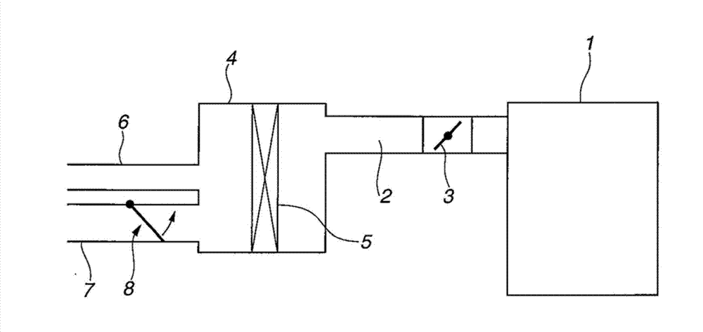
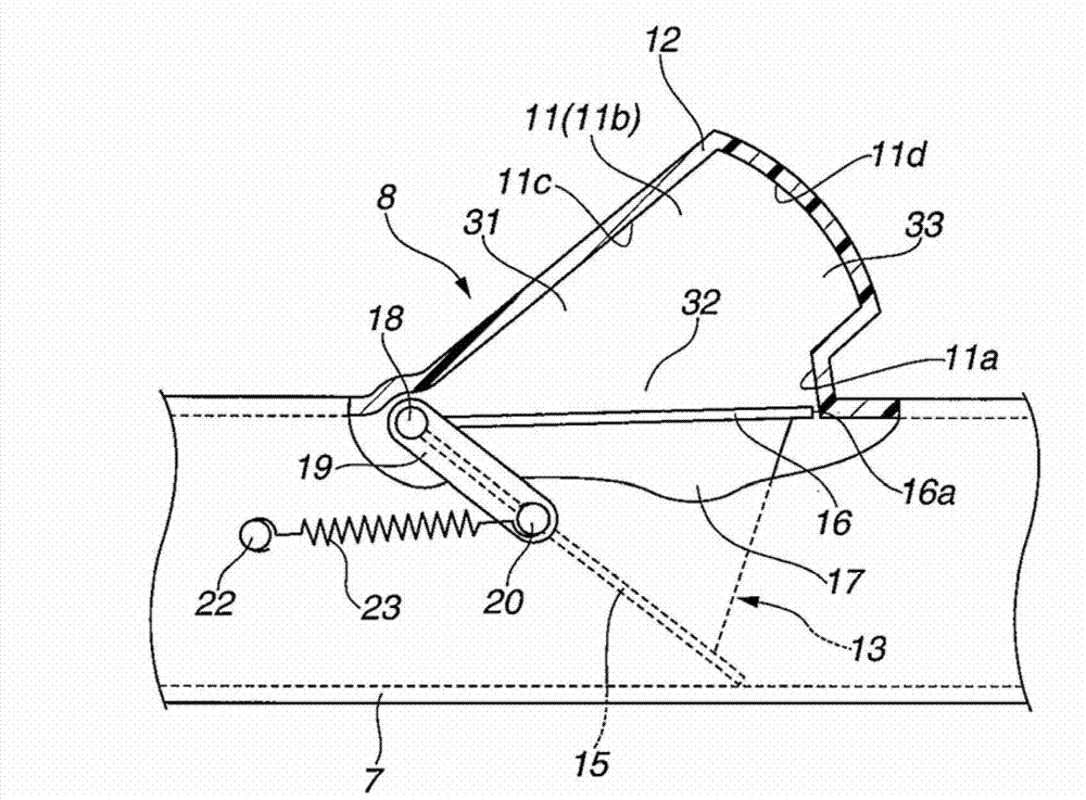
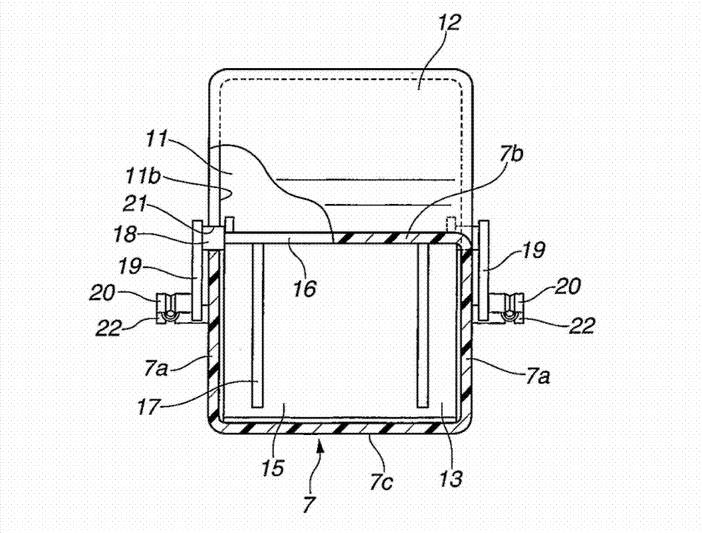
[0038] Hereinafter, an embodiment of the present invention will be described in detail based on the drawings. figure 1 It is a structural explanatory diagram schematically showing the overall structure of the air intake device of the internal combustion engine 1. For example, the air intake passage 2 connected to the air intake collector (not shown) of the internal combustion engine 1 formed by a gasoline engine is provided with a throttle. Valve 3, and the front end is connected to the air filter 4. The air cleaner 4 is divided into a so-called dust side and a clean side by an air cleaner element 5 inside, and a main air duct 6 and a sub air duct 7 serving as intake inlets are connected to the dust side. The main air duct 6 and the auxiliary air duct 7 are arranged in parallel with each other, and each front end is opened to the outside as an outside air inlet. And, one of them, for example, is provided in the sub-air duct 7 with a damper mechanism 8 for opening and closing ...


PUM


Abstract

The invention relates to an intake apparatus for internal combustion engine. The intake apparatus including two intake ducts and a flap mechanism disposed in one of the two intake ducts, the flap mechanism including a main flap, a damper flap, a damper chamber cooperating with the damper flap to form a damper space, and a biasing member biasing the main flap in a closing direction. When the main flap is located in an angular range between the fully closing position and a predetermined opening angle, a peripheral edge of the damper flap is opposed to an inner wall surface of the damper chamber with a fine clearance to thereby render the damper space substantially closed. When the main flap is located with an opening angle larger than the predetermined opening angle, a communication passage to open the damper space is formed between the inner wall surface of the damper chamber and the peripheral edge of the damper flap.

Description

technical field [0001] The present invention relates to an air intake device for an internal combustion engine, etc. for automobiles, and more particularly to an air intake device in which the effective passage cross-sectional area on the inlet side of an air cleaner is switched according to the flow rate of intake air. Background technique [0002] In internal combustion engines such as internal combustion engines for automobiles, it is known that if the passage cross-sectional area of ​​the intake air passage opened to the outside as the intake inlet of the intake system is large, the intake noise leaking to the outside is large, On the other hand, if the cross-section of the passage is too small, when the inhaled air flow rate is large, the ventilation resistance becomes large, and the inhalation efficiency decreases. [0003] Therefore, conventionally, various techniques for changing the effective passage cross-sectional area on the inlet side of the air cleaner accordin...

Claims


Application Information

Patent Timeline
Patent Type & Authority Applications(China)
IPC IPC(8): F02M35/14
CPCF02D9/16F02M35/10013F02M35/108F02M35/1222F02M35/1227
Inventor 安田裕史
Owner MAHLE FILTER SYST JAPAN CORP
Learn More