
A Cutting Channel Water Turbine

A channel-type water turbine technology, applied in the field of water turbines, can solve the problems of low efficiency and few series of impact water turbines, and achieve the effects of high efficiency, high cost performance and simple structure

Active Publication Date: 2016-05-04
宜昌光源电业有限责任公司
View PDF6 Cites 0 Cited by
  • Summary
  • Abstract
  • Description
  • Claims
  • Application Information

AI Technical Summary

Problems solved by technology

There are few series of impact turbines and their efficiency is relatively low, and they are mainly used in high water head and low flow conditions

Method used


Image

  • A Cutting Channel Water Turbine
  • A Cutting Channel Water Turbine

Examples


Embodiment 1

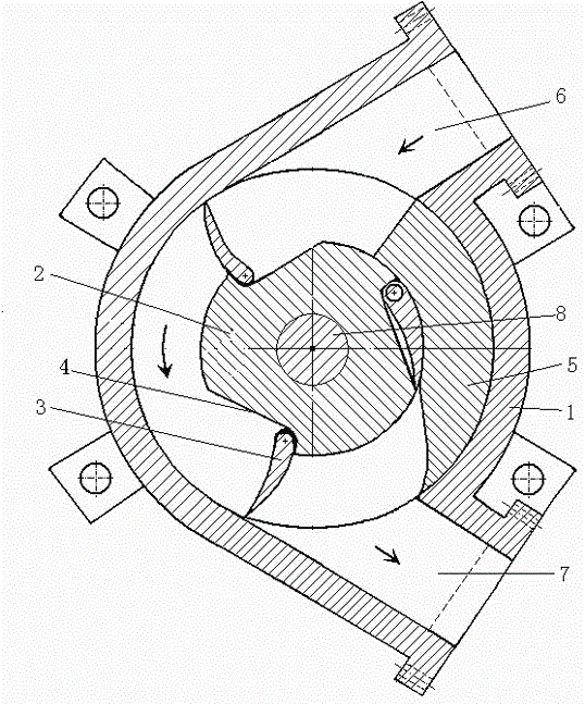
[0026] Such as figure 1 As shown, in this embodiment, it is a single tangential channel water turbine, including a casing 1 and a main shaft 8 at its center, and a runner 2 located outside the main shaft and rigidly connected with the main shaft. The runner 2 is a cylinder, and the runner 2 There are three pairs of door-shaped blades 3 evenly on the top, and a blade chamber 4 for accommodating the blades is also provided on the runner. One end of the blade chamber 4 is provided with a stopper for limiting the expansion angle of the blades. The blade chamber is used to accommodate the blades and limit the blade According to the expansion angle, the casing 1 is also provided with a partition body 5 for guiding the blades to enter the blade chamber; the partition body 5 blocks the right water flow passage of the two water flow passages in the turbine casing, leaving the left The water flow channel (or the left water flow channel is blocked, and the right water flow channel is res...

Embodiment 2

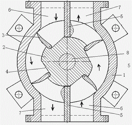
[0032] Such as figure 2 As shown, in this embodiment, it is a water turbine with double cut-off channels, including a casing 1 and a main shaft 8 at its center, and a runner 2 located outside the main shaft and rigidly connected with the main shaft. The runner 2 is evenly equipped with four movable For the blades 3 that are unfolded or folded, the runner is also provided with a blade chamber 4 for accommodating the blades when the blades are folded. One end of the blade chamber 4 is provided with a limiter for limiting the blade deployment angle. There are also two inside the casing 1. The partition body 5 used to guide the blades to be folded to enter the blade chamber; the partition body divides the annular water flow channel into two tangential flow channels on the left and right, the upper end of the left channel is set as a high-pressure water inlet, and the lower end is set as a low-pressure water outlet , the direction of water flow in the left channel is counterclockw...


PUM


Abstract

A flow-cutting channel type water turbine comprises a machine shell, a main shaft, a turning wheel, and a separation body. At least three pairs of vanes which are capable of being folded and unfolded are evenly arranged on the turning wheel. A water channel inside the water turbine is divided into one channel or more channels by the separation body. The water channel is perpendicular to a rotary shaft. A water inlet of the water channel is connected with a high-pressure water conduit. A water outlet of the water channel is connected with an exhaust water pipe. A vane chamber is arranged on each vane. A limiting portion capable of being unfolded by a certain degree is arranged on the vane chamber. The direction of high-pressure water flowing into the water channel is perpendicular to the direction of the front side of the vane when the vane is unfolded. Speed and direction of the water are the same as those of each vane and the turning wheel is pushed to rotate. Water power is efficiently converted into mechanical power by the vanes. A slope sliding block is arranged on one lateral side, with low water pressure, of the separation body, wherein the slope sliding block is capable of guiding the vanes to be folded and then enabling the vanes to enter the vane chambers of the vanes. The vanes are automatically unfolded through a spring at the position of an inlet of high-pressure water after passing through the separation body in a rotating mode. The flow-cutting channel type water turbine has the advantages of being high in efficiency, simple in structure, easy to machine and manufacture, and easy to popularize.

Description

technical field [0001] The invention belongs to the field of water turbines, and relates to a new type of water turbine, in particular to a flow channel type water turbine, which can efficiently convert water energy into mechanical energy in a small hydropower station. Background technique [0002] Water turbines are divided into two categories: impact type and impact type. The impact turbine converts the potential energy and kinetic energy of the water flow into the rotational mechanical energy of the turbine, and its runner is the core component to realize energy conversion and also a key component that determines the performance of the turbine. When the water flow passes through the blades of the runner, the magnitude and direction of the flow velocity of the water flow will change, and the water flow will give each blade a reaction force with potential energy and kinetic energy, thereby generating a rotational torque to make the runner rotate. According to the different...

Claims


Application Information

Patent Timeline
Patent Type & Authority Patents(China)
IPC IPC(8): F03B3/00F03B3/14
CPCY02E10/20Y02P70/50
Inventor 黄悦华汪德华张立仁王归新罗朝祥乔娟汪璞
Owner 宜昌光源电业有限责任公司
Learn More