Output shaft sealing device

A sealing device and output shaft technology, applied in the direction of engine sealing, transmission parts, bearing components, etc., can solve the problems of incompleteness, weakened sealing effect, oil mist leakage, etc., to achieve better sealing effect and restrain oil mist. The effect of improving the seepage and sealing effect

Active Publication Date: 2013-06-19
CRRC QISHUYAN INSTITUTE CO LTD
View PDF7 Cites 16 Cited by
  • Summary
  • Abstract
  • Description
  • Claims
  • Application Information

AI Technical Summary

Problems solved by technology

Although the technical solution of this patent has some advantages, its labyrinth sealing structure is actually a straight-through type, which is not complete enough, so the sealing effect is not ideal
In addition, the oil return is above the liquid level of the oil tank, which will easily cause oil mist to leak into the final decompression chamber along the oil return pipeline, weakening the sealing effect

Method used


Image

  • Output shaft sealing device
  • Output shaft sealing device
  • Output shaft sealing device

Examples


Embodiment 1

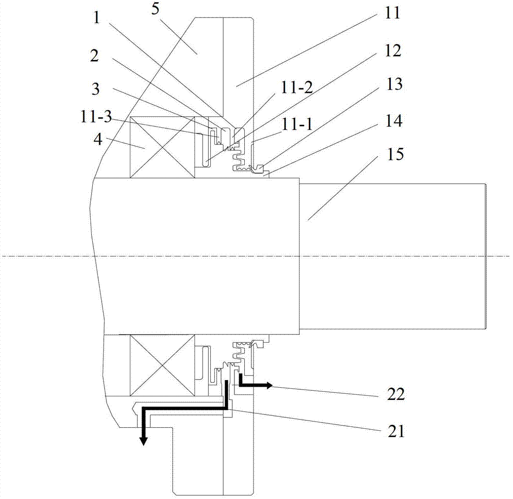
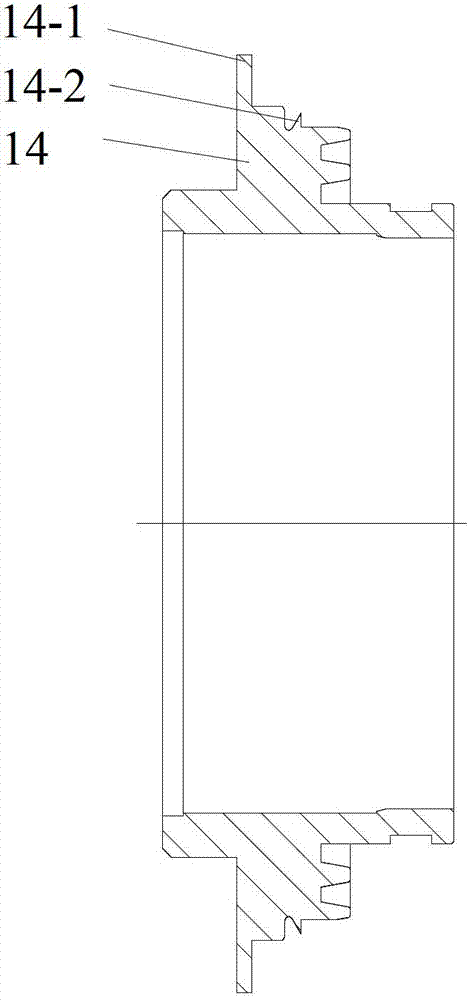
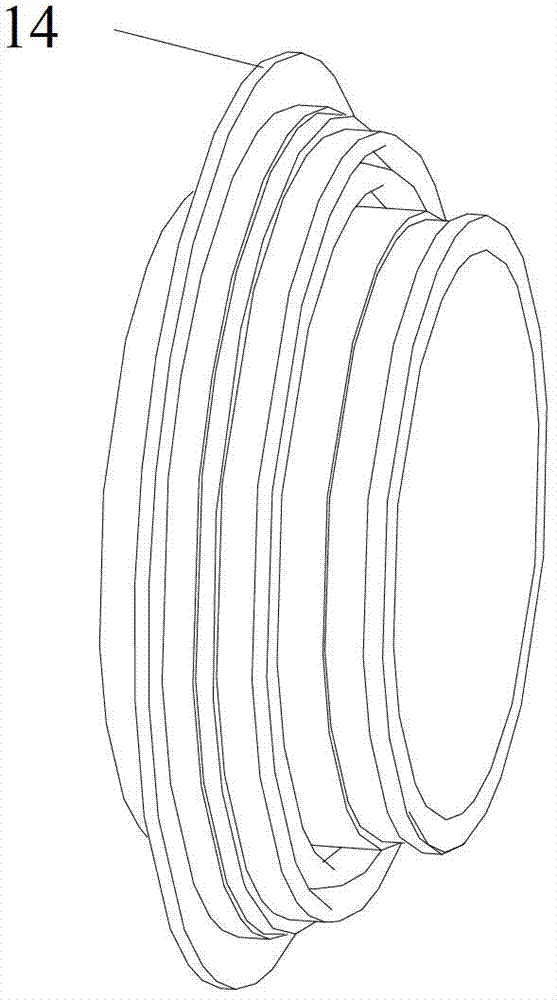
[0023] This embodiment is a wind power gearbox output shaft sealing device, the basic structure is as follows figure 1 shown (see Figures 2 to 9 ), including a sealing end cover 11 fixed on the outer end of the output hole of the box body 5, and a high-speed output shaft 15 supported in the output hole bearing 4 and passing through the sealing end cover 11 . The output shaft 15 is fixedly connected with the labyrinth inner ring 14 located in the inner hole of the sealing end cover 11 . The inner hole of the sealing end cap 11 has an outer blocking wall 11-1, a middle blocking wall 11-2, and an inner blocking wall 11-3 extending radially inward. Between the outer blocking wall 11-1 and the middle blocking wall 11-2 and between the middle blocking wall 11-2 and the inner blocking wall 11-3 respectively form an annular groove-shaped third oil return chamber 1 and a second oil return chamber 2 . The output hole is embedded between the oil deflector ring 12 outside the bearing a...


PUM


Abstract

The invention relates to an output shaft sealing device and belongs to the technical field of wind power generation. The output shaft sealing device comprises a sealing end cover and an output shaft penetrating out of the sealing end cover. A maze inner ring is fixedly connected on the output shaft. An inner hole of the sealing end cover is provided with an outer blocking wall, an intermediate blocking wall and an inner blocking wall. A third oil return cavity is formed between the outer blocking wall and the intermediate blocking wall and a second oil return cavity is formed between the intermediate blocking wall and the inner blocking wall. A first oil return cavity is formed between an oil blocking ring, embedded outside a bearing, in an output hole and the inner blocking wall. The inner holes of the outer blocking wall, the intermediate blocking wall, the inner blocking wall and the oil blocking ring form an axial maze. An inwards protruding ring is arranged on the inner end face of the outer blocking wall. The inwards protruding ring and an outwards protruding ring form a radial maze, wherein the maze inner ring corresponds to the position of the outwards protruding ring. A sealing ring, with a V-shaped section, located outside the outer blocking wall is installed on the maze inner ring. According to the output shaft sealing device, the axial maze forms a step type with various heights and is matched with the interlaced-type radial maze and an oil return channel of the final stage is directly connected below the liquid level of lubrication oil, so that oil mist leakage is effectively inhibited and the sealing effect is better.

Description

technical field [0001] The invention relates to a sealing device, in particular to a sealing device for a high-speed output shaft of a gearbox in a wind power generation system, and belongs to the technical field of wind power generation. Background technique [0002] Wind power gearboxes, also known as wind power gearboxes, are usually installed on towers with a height of 65-80m. The working environment is harsh and the maintenance cost is extremely high. The design life of a wind power gearbox is usually 20 years, so the reliability requirements for each part are very high. If oil leakage occurs during work, it will not only have a bad impact on the environment, but will also incur high cleaning costs. Therefore, the leakage of wind power gearboxes is a serious hidden danger for both OEMs and end users. [0003] The high-speed output shaft of the wind power gearbox has a high speed (usually 1500 to 2000r / min), and it also needs to bear a large torque, resulting in high he...

Claims


Application Information

Patent Timeline
Patent Type & Authority Applications(China)
IPC IPC(8): F16J15/447F16H57/029F03D11/00
CPCF16C33/80F16C35/06Y02E10/72
Inventor 张亚楠靳国忠王志勇刘显高
Owner CRRC QISHUYAN INSTITUTE CO LTD
Why Eureka
Try Eureka