
Air conditioner, RS485 bus system thereof and bus system control method

A RS485, bus system technology, applied in the field of industrial control, can solve the problems of increasing the difficulty of engineering wiring, more cable consumables, and increasing costs, and achieve the effects of reducing engineering installation difficulty, low failure rate, and reducing cable costs

Active Publication Date: 2013-06-19
GREE ELECTRIC APPLIANCES INC
View PDF6 Cites 14 Cited by
  • Summary
  • Abstract
  • Description
  • Claims
  • Application Information

AI Technical Summary

Problems solved by technology

The problems existing in the four-wire connection structure in the prior art are: two separate power lines are required, and the cable consumables are more, which increases the cost; when wiring, the order of the four lines needs to be identified, which increases the difficulty of engineering wiring and increases the probability of errors

Method used


Image

  • Air conditioner, RS485 bus system thereof and bus system control method
  • Air conditioner, RS485 bus system thereof and bus system control method
  • Air conditioner, RS485 bus system thereof and bus system control method

Examples


Embodiment Construction

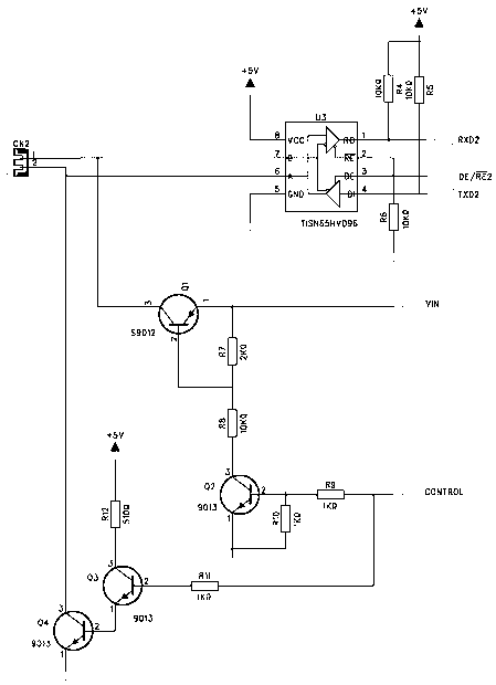
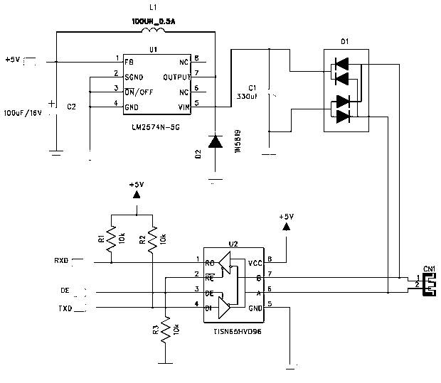
[0029] see Figure 1~2 , The RS485 bus system of the present invention includes a connected power supply side circuit and a power taker side circuit.

[0030] Such as figure 1 As shown, the power supply circuit includes a two-core needle seat CN2 connected to the wire controller cable, and its control terminal control terminal is connected to the IO of the MCU. When the MCU outputs a high level, the power interface Vin is connected to the 24V power supply, and connected to the two-core Pin 1 of needle seat CN2 is turned on, and there is a 24V power supply on the bus at this time; the ground interface is turned on with pin 2 of the two-pin needle seat CN2, and connected to the ground; at this time, it is power supply time, and power can be taken through the bus When the MCU outputs a low level, Vin and GND are disconnected from the 24V power supply and GND respectively. At this time, there is no additional power supply on the bus, and normal communication can be carried out. ...


PUM


Abstract

The invention provides an RS485 bus system which comprises a power supplier circuit and a power taker circuit, and the power supplier circuit and the power taker circuit are connected with each other. The power supplier circuit comprises a double-core needle base CN2 which is connected with wired controller cables, one end of the double-core needle base CN2 is connected with a grounding port, and the other end of the double-core needle base CN2 is communicated with a power supply port. The power supplier circuit further comprises a control end which is connected with an input / output (IO) of a microprogrammed control unit (MCU). The power taker circuit comprises a double-core needle base CN1 which is connected with mainboard cables, two pins of the double-core needle base CN1 are connected with a rectifier bridge in a crossed mode and are connected with an energy storage capacitor and a power supply chip, the double-core needle base CN2 of the power supplier circuit and the double-core needle base CN1 of the power taker circuit are respectively connected with a communication circuit. The invention further provides a bus system control method which uses the RS485 bus system. The bus system control method includes the following steps: controlling an input level value of the MCU, controlling the power taker circuit to communicate or not, and enabling the energy storage capacitor to take power or discharge power. The RS485 bus system and the bus system control method aim at a small-sized terminal device which is smaller in power, double core wires are adopted to achieve the functions of supplying power and communicating, half cable cost is reduced, and engineering installation difficulty and failure rate are greatly reduced.

Description

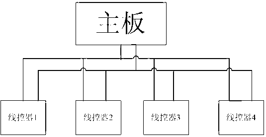
[0001] 【Technical field】 [0002] The invention relates to the field of industrial control, in particular to an RS485 bus system in the field of air conditioning. [0003] 【Background technique】 [0004] Due to the advantages of long transmission distance, strong anti-interference ability and low cost, RS485 bus is widely used in industrial control, air conditioning and other fields. In the low-power small terminal equipment of the air conditioner, such as a wire controller, the wire controller communicates with the motherboard of the internal unit, and the wire controller needs to be powered by the motherboard, so four wires are required to connect the motherboard and the wire controller, two of which One is the power cord, that is, the motherboard supplies power to the wire controller, and the other two are communication lines. The problems existing in the four-wire connection structure in the prior art are: two separate power wires are required, and the cable consumable...

Claims


Application Information

Patent Timeline
IPC IPC(8): F24F11/00F24F11/02G05B19/418
Inventor 吴学伟赵志刚唐政清邹宏亮
Owner GREE ELECTRIC APPLIANCES INC
Learn More