
Solar energy bundling condensation supporting device

A support device, solar energy technology, applied in solar thermal devices, solar thermal power generation, heating devices, etc., can solve the problems of different degrees of warp and latitude deflection, low safety factor, large weight, etc., to achieve the effect of simplifying the control theory

Inactive Publication Date: 2013-06-19
深圳市阳能科技有限公司
View PDF9 Cites 3 Cited by
  • Summary
  • Abstract
  • Description
  • Claims
  • Application Information

AI Technical Summary

Problems solved by technology

This method is easy to control one mirror, but two motors are needed to control one mirror, so M×N×2 motors are needed to control the second reflection mirror of M×N mirror arrays
Moreover, for each mirror, there are different controls for latitude and longitude deflection, which is obviously very complicated
Even if it is simplified to M+N control units, it still has multiple motors, which not only has high cost and heavy weight, but also requires multiple motors to be tested separately during maintenance. The detection situation is complicated and the safety factor is low.

Method used


Image

  • Solar energy bundling condensation supporting device
  • Solar energy bundling condensation supporting device
  • Solar energy bundling condensation supporting device

Examples


Embodiment Construction

[0026] In order to make it easier for those skilled in the art to understand and implement the present invention, the present invention will be further described in detail below in conjunction with the accompanying drawings and specific embodiments.

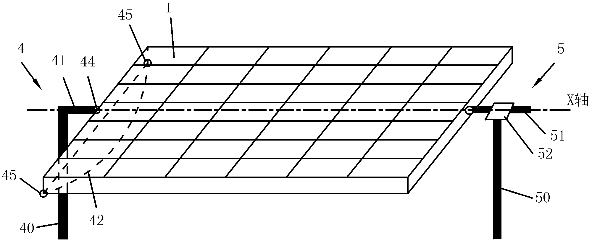
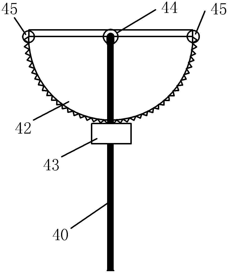
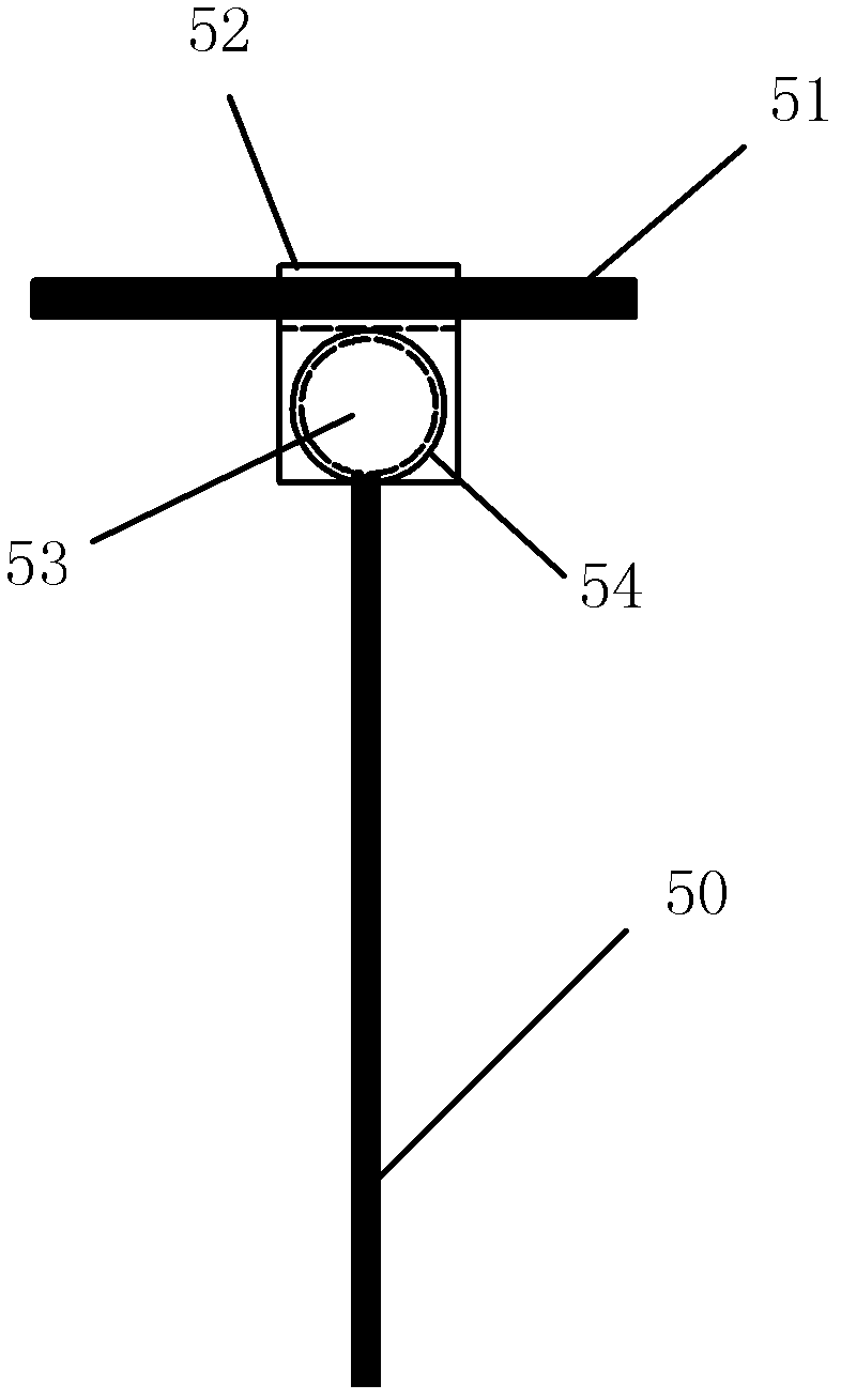
[0027] figure 1 Shown is a schematic diagram of the solar energy concentrating support device and its mirror array frame of the present invention. Each mirror array is composed of M rows×N columns of condenser mirror units, and the entire mirror array is arranged on a bracket to form a mirror array frame together. The solar energy concentrating support device of the present invention includes a rotating assembly 4 and a lifting assembly 5. The rotating assembly 4 is used to control the entire mirror array to turn 180° to track the rising and setting of the sun, and the lifting assembly 5 is used to control the inclination angle of the entire mirror array to track the sun. Seasons of the year change. figure 1 Shown rotating assem...


PUM


Abstract

The invention relates to a solar energy bundling condensation supporting device which is installed on a bundling condensation lens array. The solar energy bundling condensation supporting device comprises a rotating component and a lifting component, wherein the rotating component controls rolling-over of the lens array, and the lifting component controls the dip angle of the lens array. The rotating component comprises a fixed post, a transverse rod, a semicircular rotating wheel and a stepping motor, wherein the transverse rod is perpendicularly connected with the fixed rod, the periphery of the semicircular rotating wheel is provided with thin teeth, and the stepping motor is matched with the thin teeth. The transverse rod is rotationally connected with the lens array, and two ends of the rotating wheel are rotationally connected with two ends of the lens array. The lifting component comprises a hydraulic lifting post, a numerical control motor, a transverse beam, a ball shaft sleeve and a ball, wherein the numerical control motor controls lifting, the transverse beam is fixedly connected with the lens array, the ball shaft sleeve is sleeved on the transverse beam, and the ball is installed on the lower portion of the ball shaft sleeve and can freely rotate inside the lower portion of the ball shaft sleeve. The bottom of the ball shaft sleeve is provided with a through groove, the numerical control motor controls lifting of the hydraulic lifting post, and the hydraulic lifting post can freely move inside the through groove. The solar energy bundling condensation supporting device is controlled by a controller in a centralized mode, simplifies the control theory of the lens array, and can accurately control that the lens array tracks the sun.

Description

technical field [0001] The invention relates to a solar energy concentration concentrator supporting device, which is used for controlling a solar energy concentration concentrator array, and is widely used in the fields of solar thermal power generation, solar air conditioning, heating, hot water and the like. Background technique [0002] Historically, in solar systems that track the sun head-on, since the mirror array and mirrors have M×N control points, a series of problems such as equipment investment cost, total equipment weight, wind resistance, and sandstorms have always plagued solar thermal utilization. , especially the difficulties in realizing the commercialization of large-scale solar thermal power generation. Some experts broke the traditional sun tracking method using azimuth-elevation angle, and proposed a tracking formula using spin-elevation angle, using a computer control system to simplify M×N control units into M+N control units, that is, M×N N mirrors ...

Claims


Application Information

Patent Timeline
Patent Type & Authority Applications(China)
IPC IPC(8): F24J2/54
CPCY02E10/47
Inventor 陈展和
Owner 深圳市阳能科技有限公司
Learn More