Total station point location centering indicator
A total station and indicator technology, which is applied in the field of total station alignment indicator to achieve the effects of improving cheapness and reducing errors
- Summary
- Abstract
- Description
- Claims
- Application Information
AI Technical Summary
Problems solved by technology
Method used
Image
Examples
Embodiment 1
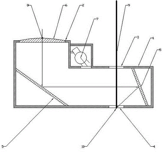
[0015] Such as figure 1 As shown, the present invention includes a housing 1, and the housing 1 is provided with an observation port 2, a light entrance 3, a sample setting port 4 and a lighting lamp 7, and the light entrance 3 and the position of the sample setting port 4 are Correspondingly, and all are rectangular; the housing 1 is also fixedly provided with a reflective imaging group and a magnifying glass 6 adapted to the observation port 2, and a center mark 8 is provided at the center of the magnifying glass 6, and the The reflection imaging group is composed of two plane mirrors 5 fixedly arranged inside the housing 1, and the angle of the two plane mirrors 5 in the horizontal direction can be determined according to the specific position of the sample setting port 4 on the housing ; Before positioning the total station, the same point 10 needs to be set on the ground, and the infrared rays 9 sent by the total station pass through the light entrance 3 and the sample se...
Embodiment 2
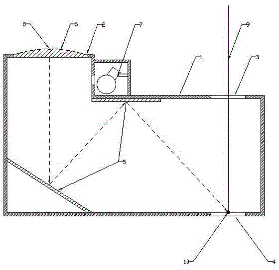
[0017] Such as figure 2 As mentioned above, this embodiment is basically the same as Embodiment 1, the difference is that the positions of the two flat mirrors 5 that make up the reflection imaging group are different, and it can still reflect the infrared rays 9 to the 10 places of the sample point, to achieve the purpose of centering; so any combination of two flat mirrors 5 to achieve the purpose of reflecting the infrared ray 9 to the 10 places of the sample point, all belong to the equivalent technical solution of the present embodiment .
Embodiment 3
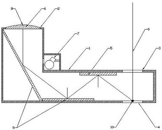
[0019] Such as image 3 As shown, this embodiment is basically the same as Embodiment 1, the difference is that the reflective imaging group is composed of three plane mirrors 5 arranged in the housing 1, and the three plane mirrors 5 are connected to the horizontal The angle of direction can be determined according to the specific position of the sample setting port 4; so any combination of three or more than three flat mirrors 5 can be used to reflect the infrared ray 9 to the sample point 10. Purposes all belong to the equivalent technical solutions of this embodiment.
PUM
 Abstract
Description
Claims
Application Information
 - R&D
- Intellectual Property
- Life Sciences
- Materials
- Tech Scout
- Unparalleled Data Quality
- Higher Quality Content
- 60% Fewer Hallucinations
Browse by: Latest US Patents, China's latest patents, Technical Efficacy Thesaurus, Application Domain, Technology Topic, Popular Technical Reports.
© 2025 PatSnap. All rights reserved.Legal|Privacy policy|Modern Slavery Act Transparency Statement|Sitemap|About US| Contact US: help@patsnap.com


