On-board suspension type bearing bracket
A carrier frame and suspension technology, which is applied to railway car body parts, transportation and packaging, etc., can solve the problems of reducing the utilization rate of train interior space, poor flexibility of vehicle-mounted equipment combination layout, and unfavorable equipment efficiency, etc., so as to enhance cheapness, Improved space utilization and improved operability
- Summary
- Abstract
- Description
- Claims
- Application Information
AI Technical Summary
Problems solved by technology
Method used
Image
Examples
Embodiment 1
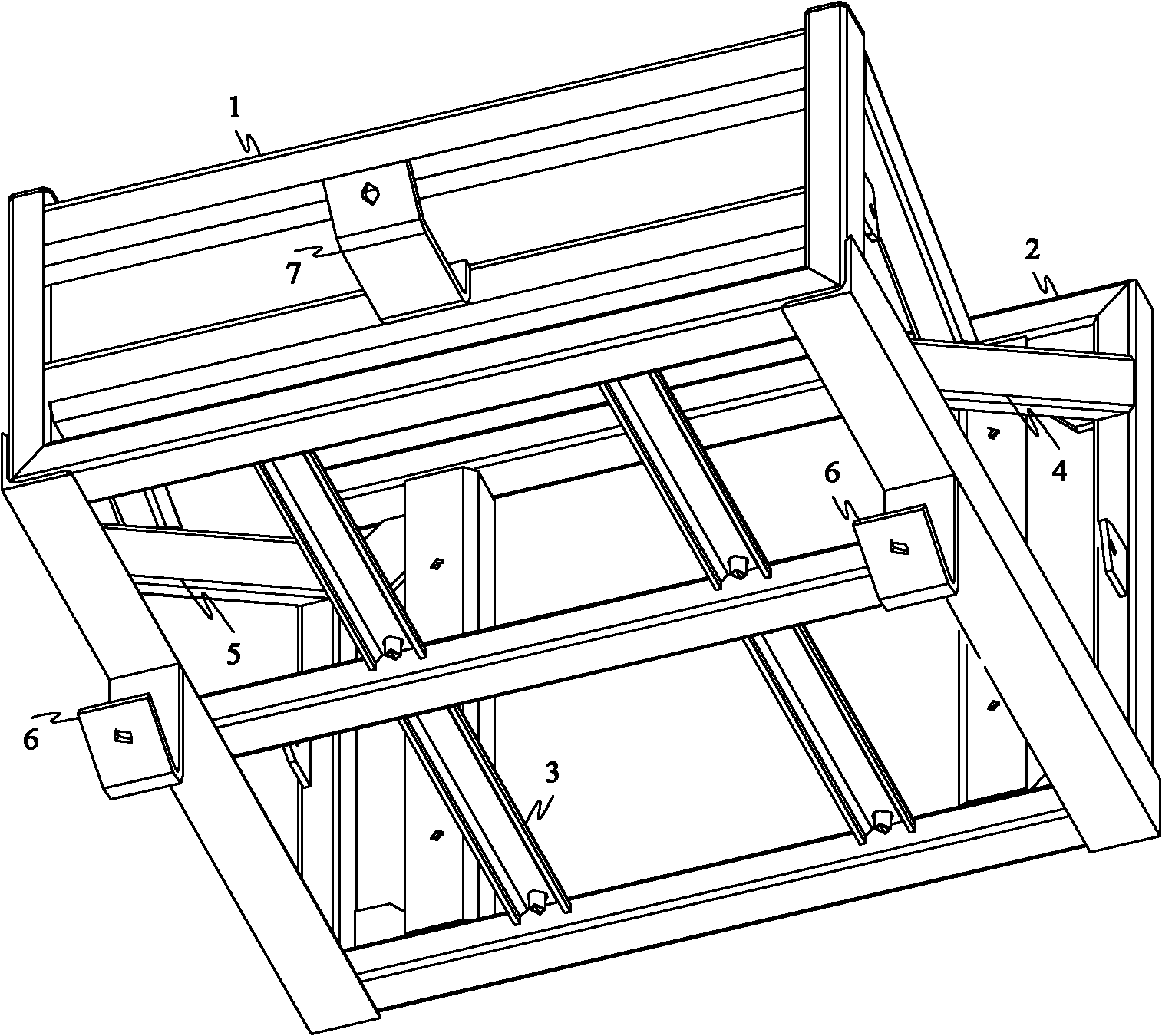
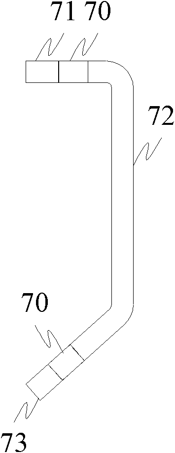
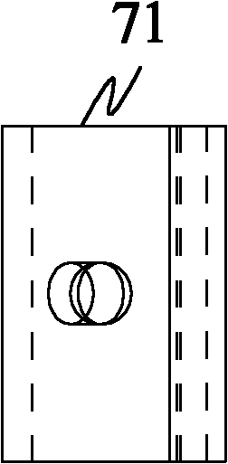
[0033] like Figure 1-4 As shown, the present invention provides a vehicle-mounted suspension carrier, including a carrier body, a side wall connector 6 and a roof connector 7, wherein the carrier body includes a roof for connecting to the roof through the roof connector 7. The surface frame 1, the bottom frame 2 opposite to the top frame 1 and arranged at intervals, and the second side frame 4, the first side frame 3 and the third side frame arranged between the top frame 1 and the bottom frame 2 and connected in sequence 5 (the upper side and the lower side of the second side frame 4, the first side frame 3 and the third side frame 5 can also stretch out the top frame 1 and the bottom frame 2), adopt the structure that the side frames are connected in sequence It is beneficial to save material, so that the side frames of the same size are connected with the top frame 1 and the bottom frame 2 to obtain the largest internal space, wherein the top frame 1, the bottom frame 2 an...
Embodiment 2
[0037] like Figure 5 As shown, because the roof surface is a curved surface, in order to make the connection between the carrier frame and the roof surface more stable, two roof connectors 7 are provided, which are the first roof connector 71' and the second roof connector 71' respectively. The top connector 72', the two roof connectors 7 form a group so that the bottom frame is fixed in the horizontal direction; in this embodiment, the two roof connectors 7 are formed along the top frame 1 and the second side frame 4 or The sides connected to the third side frame 5 are arranged at intervals in the length direction, wherein the standing portion 72 of the first roof connecting body 71 ′ close to the first side frame 3 is relatively far away from the second side of the first side frame 3 . The standing portion 72 of the roof connecting body 72' is relatively short.
Embodiment 3
[0039] like Figure 6-14 As shown, in order to make the side wall connecting body 6 more stable and fixedly connected to the first side frame 3, the end of the horizontal part 61 connected to the first side frame 3 is provided with a connecting plate 63, and the connecting plate 63 is connected by a bolt assembly. It is connected with the first side frame 3 , and the supporting rib 64 is welded between the horizontal portion 61 and the connecting plate 63 . The arrangement of the supporting ribs 64 increases the strength of the side wall connecting body 6 . There are two side wall connectors 6 , and the connecting plates 63 are respectively fixed on opposite sides of the first side frame 3 . The two sides are respectively close to the two adjacent sides of the first side frame, the second side frame and the third side frame.
[0040] Two groups of roof connectors 7 are arranged on the top frame 1 , and the two groups of roof connectors 7 are arranged at intervals along the s...
PUM
 Abstract
Description
Claims
Application Information
 - R&D
- Intellectual Property
- Life Sciences
- Materials
- Tech Scout
- Unparalleled Data Quality
- Higher Quality Content
- 60% Fewer Hallucinations
Browse by: Latest US Patents, China's latest patents, Technical Efficacy Thesaurus, Application Domain, Technology Topic, Popular Technical Reports.
© 2025 PatSnap. All rights reserved.Legal|Privacy policy|Modern Slavery Act Transparency Statement|Sitemap|About US| Contact US: help@patsnap.com


