
Bridge health monitoring system provided with power supply fault message prompting function

A technology for bridge health monitoring and power supply failure, which is used in the testing of machinery/structural components, measuring electricity, measuring devices, etc. It can solve the problem of inability to send and realize timely monitoring of power supply conditions of bridge monitoring instruments, fault warning, and poor data accuracy. and other problems, to achieve the effect of complete functions, ensuring timeliness and scientificity, and high degree of intelligence

Inactive Publication Date: 2013-06-19
XIAN CENTN TECH
View PDF0 Cites 2 Cited by
  • Summary
  • Abstract
  • Description
  • Claims
  • Application Information

AI Technical Summary

Problems solved by technology

However, how to effectively ensure the normal and stable power supply of various instruments on the bridge has become an urgent problem to be solved. Traditional bridge health monitoring systems use manual recording and processing of power supply stability, or use wired optical cables to establish connections. Data accuracy is not good
Moreover, there is often a certain time delay in the online transmission of data, and many of them need to use a pair of photoelectric isolation long-line drivers to connect with the front control machine with a long communication cable to transmit the data back to the control and analysis terminal in the room. It is impossible to realize timely monitoring and fault warning of the power supply status of bridge monitoring instruments, and it cannot be sent to the management terminal users in real time

Method used


Image

  • Bridge health monitoring system provided with power supply fault message prompting function

Examples


Embodiment Construction

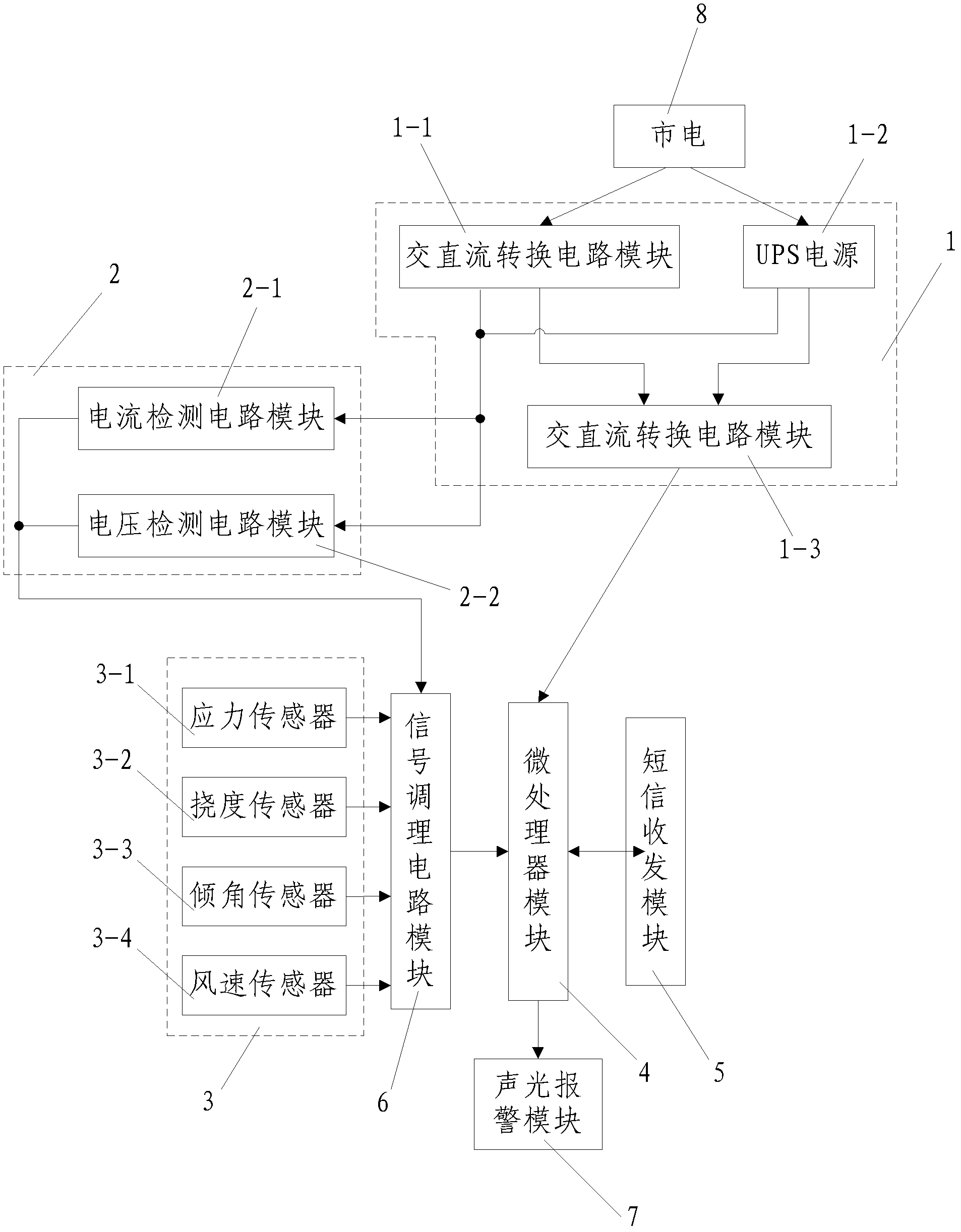
[0025] Such as figure 1 As shown, the present invention includes a bridge health monitoring system with a power supply failure short message prompt function, including a power supply unit 1, a power supply failure detection unit 2 connected to the power supply unit 1, a sensor group 3 for collecting bridge health conditions, and The power supply failure detection unit 2 is connected with the sensor group 3 and is used to analyze and process the bridge health status and the power supply situation and the short message transceiver module 5 connected with the microprocessor module 4, and the microprocessor module The input terminal of 4 is connected with a signal conditioning circuit module 6 for conditioning the signals output by the power supply failure detection unit 2 and the sensor group 3, and the input terminal of the signal conditioning circuit module 6 is connected with the power supply failure detection unit 2 and the sensor group 3 connected; the power supply unit 1 in...


PUM


Abstract

The invention discloses a bridge health monitoring system provided with a power supply fault message prompting function. The bridge health monitoring system provided with the power supply fault prompting function comprises a power supply unit, a power supply fault detecting unit, a sensor group, a microprocessor module and a message receiving and sending module, wherein the power supply fault detecting unit is connected with the power supply unit, the microprocessor is connected with the power supply fault detecting unit and the sensor group and is used for analyzing and handling bridge health conditions and power supply conditions, and the message receiving and sending module is connected with the microprocessor module. The input end of the microprocessor module is connected with a signal conditioning circuit module. The power supply comprises an alternating current direct current circuit converting module, an UPS power source and a power automatic converting module. The sensor group comprises a stress sensor, a deflection sensor, an included angle sensor and an air speed sensor. The bridge health monitoring system provided with the power supply fault prompting function can monitor power supply fault in a real time mode and informs relative workers through the message when faults appear. The bridge health monitoring system provided with the power supply fault prompting function is reasonable in design, complete in functions, high in intelligentized degree and wide in popularization and application.

Description

technical field [0001] The invention relates to the technical field of bridge health monitoring, in particular to a bridge health monitoring system with a short message prompt function for power supply failure. Background technique [0002] At present, due to the scattered areas of bridge construction across the country, most of which are located in remote areas, and most of the bridge sites are high-altitude operations, the instant notification of power supply failures in the bridge health monitoring system has become a major problem in the monitoring industry. [0003] The overall health monitoring of the bridge's own environment is the need for bridge operation safety that is increasingly valued. The health of the bridge's own parameter data can help the national bridge management agency to make important decisions in a timely manner on the safety and hidden dangers of the bridge. However, how to effectively ensure the normal and stable power supply of various instrument...

Claims


Application Information

Patent Timeline
IPC IPC(8): G01D21/02G01M99/00G01R31/00
Inventor 陈学锋
Owner XIAN CENTN TECH
Learn More