Optical current sensor and current measurement method based on comparative measurement structure

A current sensor, comparative measurement technology, applied in the direction of measuring current/voltage, measuring electrical variables, measuring devices, etc., can solve the problem of inaccurate measurement results of wire current, eliminate the influence of Feld's constant, reduce Feld's constant, etc. Constant error, the effect of avoiding errors

Inactive Publication Date: 2013-06-19
HARBIN INST OF TECH
View PDF9 Cites 12 Cited by
  • Summary
  • Abstract
  • Description
  • Claims
  • Application Information

AI Technical Summary

Problems solved by technology

[0003] The purpose of the present invention is to solve the problem that in the existing optical current sensor, the Verdet constant of the magneto-optical material is affected by the temperature change, which causes the measurement result of the wire current to be inaccurate, and provides an optical current sensor based on a comparative measurement structure. Sensor and method for measuring current

Method used


Image

  • Optical current sensor and current measurement method based on comparative measurement structure
  • Optical current sensor and current measurement method based on comparative measurement structure
  • Optical current sensor and current measurement method based on comparative measurement structure

Examples


specific Embodiment approach 1

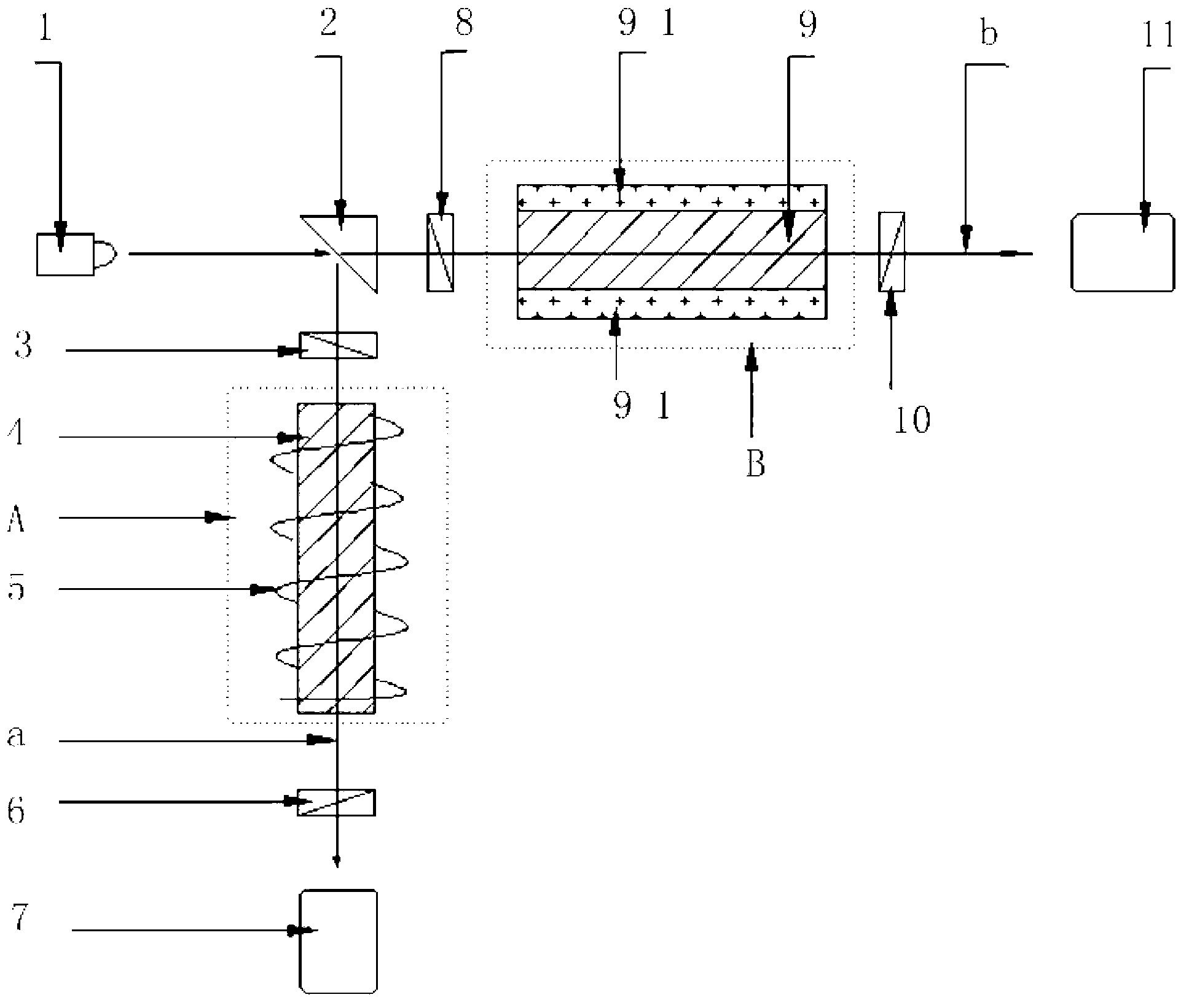
[0021] Specific implementation mode one: the following combination figure 1 Describe this embodiment, the optical current sensor based on the comparative measurement structure described in this embodiment, it includes laser generator 1, beam splitter 2, first polarizer 3, first magneto-optical glass 4, energized coil 5, first detector Polarizer 6, first photodetector 7, second polarizer 8, second magneto-optical glass 9, second analyzer 10 and second photodetector 11,

[0022] The energized coil 5 is helically wound on the outer surface of the first magneto-optic glass 4 to form the measuring arm B of the sensor; the upper surface and the lower surface of the second magneto-optic glass 9 are provided with a flat permanent magnet 9-1, the second The magneto-optical glass 9 and the flat permanent magnet 9-1 form the reference arm A of the sensor, and the reference arm A and the measuring arm B are vertically arranged, and the reference arm A is perpendicular to the upper surface...

specific Embodiment approach 2

[0028] Embodiment 2: This embodiment further describes Embodiment 1. The first magneto-optical glass 4 and the second magneto-optic glass 9 in this embodiment are the same magneto-optic glass 9 .

[0029] In this embodiment, the constituent materials of the first magneto-optical glass 4 and the second magneto-optic glass 9 are exactly the same, that is, the constituent substances have the same concentration and the same size.

specific Embodiment approach 3

[0030] Specific implementation mode three: this implementation mode is a method for measuring current using the optical current sensor based on the comparative measurement structure described in the first or second implementation mode,

[0031] From the Faraday deflection angle of the first magneto-optical glass 4 in the measuring arm B

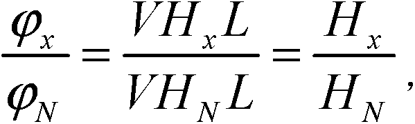
[0032] Wherein V is the Verdet constant of the first magneto-optical glass 4 and the second magneto-optic glass 9, H x Be the magnetic field intensity of the first magneto-optical glass 4, L is the length of the first magneto-optic glass 4 and the second magneto-optic glass 9,

[0033] Faraday deflection angle through the second magneto-optical glass 9 in the reference arm A

[0034] h N Be the magnetic field strength of the second magneto-optical glass 9,

[0035] Divide the above two equations to get:

[0036]

[0037] By the Faraday deflection angle of the first magneto-optical glass 4 The Faraday deflection angle of the secon...


PUM


Abstract

The invention belongs to the technical field of optical current sensors, discloses an optical current sensor and a current measurement method based on a comparative measurement structure and aims to solve the problem that a measurement result of a lead current is inaccurate because the Verdet constant of a magneto-optical material in the conventional optical current sensor is influenced by temperature change. A laser beam emitted by a laser generator of the sensor is subjected to light splitting by a light splitter to form a measurement light beam and a reference light beam, wherein the measurement light beam is transmitted to first magneto-optical glass, a first polarization analyzer and a first photoelectric detector sequentially after being polarized by a first polarizer; and the reference light beam is transmitted to second magneto-optical glass, a second polarization analyzer and a second photoelectric detector after being polarized by a second polarizer. By the method, the magnetic field intensity of the first magneto-optical glass is acquired according to Faraday deflection angles of the first magneto-optical glass and the second magneto-optical glass and the magnetic field intensity of the second magneto-optical glass, so that a value of current in an electrified coil is obtained. The sensor is applied to measurement of the current in the electrified coil.

Description

technical field [0001] The invention relates to an optical current sensor based on a comparative measurement structure and a method for measuring current, belonging to the technical field of optical current sensors. Background technique [0002] In the optical current sensor, the Faraday deflection angle φ=VHL of light passing through the magneto-optic material, where V is the Verdet constant of the magneto-optic material, H is the magnetic field strength, L is the length of the magneto-optic material, and the Faraday deflection angle φ is obtained by measurement , so that under the condition of knowing the Verdet constant V and the length L of the magneto-optical material, the magnetic field strength H can be calculated, and then the wire current can be calculated by Ampere's loop law. In this traditional method, the Verdet constant V will be affected by temperature changes, which will lead to errors in the obtained magnetic field strength H, and thus lead to inaccurate mea...

Claims


Application Information

Patent Timeline
Patent Type & Authority Applications(China)
IPC IPC(8): G01R19/00
Inventor 申岩于文斌张国庆郭志忠路忠峰
Owner HARBIN INST OF TECH
Why Eureka
Try Eureka