Male Connectors and Electrical Connectors

A technology of electrical connectors and connectors, which is applied in the direction of connection, parts of connection devices, circuits, etc., can solve the problems of loose connections, affecting the connection of connection terminals, poor contact, etc., and achieve the effect of stable connection and quality assurance

Active Publication Date: 2015-09-30
SHENGLAN TECH CO LTD
View PDF5 Cites 1 Cited by
  • Summary
  • Abstract
  • Description
  • Claims
  • Application Information

AI Technical Summary

Problems solved by technology

[0003] During actual use, the applicant found that the puncture-type electrical connector has the following problems: (1) The connection between the connection terminal and the plastic body is not firm enough, and the connection terminal may slide relative to the plastic body. When sliding, the connection between the connection terminal and the conductive terminal or the wire core is easy to loosen, resulting in poor contact, which causes intermittent interruption of the signal transmitted between the conductive terminal and the wire, which seriously affects the quality of signal transmission; The surface of the connection terminal is oxidized, or the male connector is frequently plugged and pulled out, or the environment with frequent temperature changes causes frequent changes in thermal expansion and contraction. In these cases, the problem of poor contact is more obvious
(2) The connection terminal of the prior art includes a front clamping part, a rear clamping part, a clamping part and a linear main body, and the front clamping part and the rear clamping part are fixed on one side of the linear main body, clamping The part is fixed on the other side of the linear main body; when the conductive terminal is inserted into the clamping part of the connecting terminal, the thrust will be transmitted along the front of the linear main body to the rear, which may make the rear part of the connecting terminal and the wire The wire core produces relative movement, which affects the connection between the rear of the terminal and the core of the wire, thereby increasing the probability of poor contact; while pulling the wire connected to the rear of the terminal, the pulling force will be along the direction of the linear body. The rear part is transmitted to the front part, which may cause relative movement between the front part of the connection terminal and the conductive terminal, affecting the connection between the front part of the connection terminal and the conductive terminal, thereby increasing the probability of poor contact; the process of inserting and pulling the wire more prone to poor contact
(3) The connection terminal and the wire core are connected by piercing. When the wire is repeatedly pulled by external force, the wire core and the front clamping part and the rear clamping part will produce relative movement, resulting in the connection terminal and the wire core. Poor contact
(4) The connection between the wire and the connection terminal is exposed, and the connection is easy to contact with the external conductor and cause a failure. When the wire is bent upward, the connection is easy to loosen, resulting in poor contact

Method used


Image

  • Male Connectors and Electrical Connectors
  • Male Connectors and Electrical Connectors
  • Male Connectors and Electrical Connectors

Examples


Embodiment 1

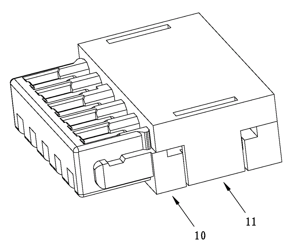
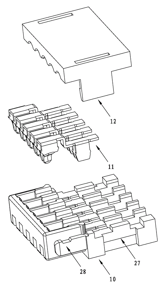
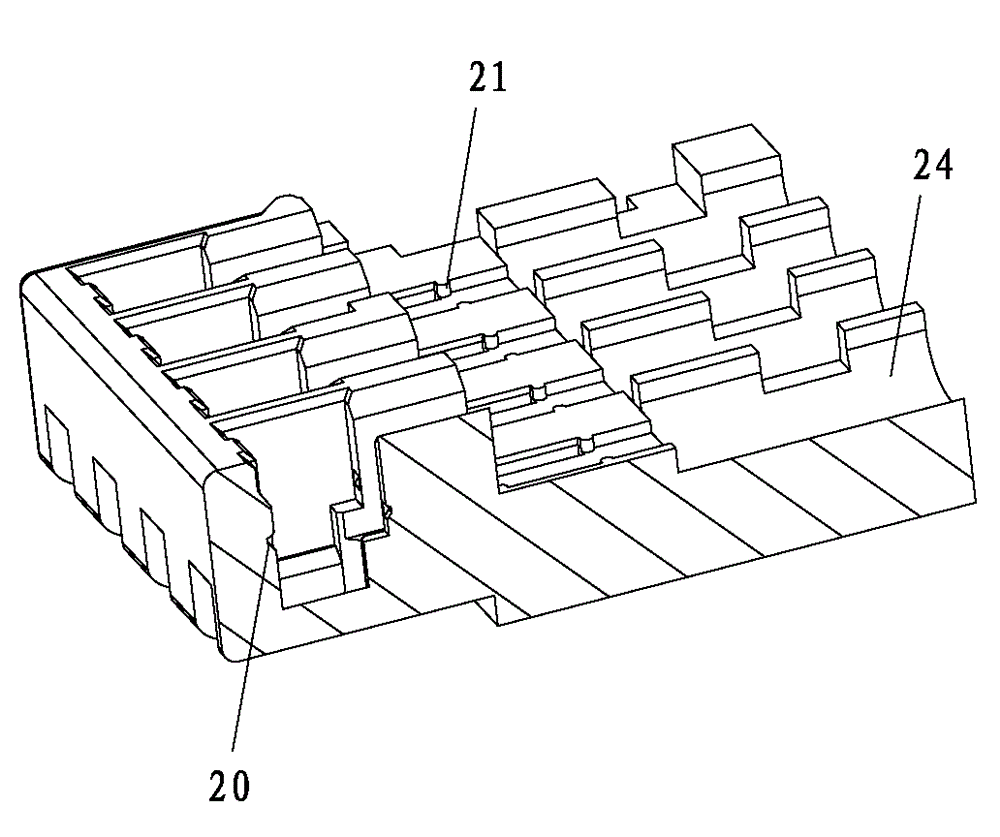
[0038] See Figure 1 to Figure 11 , the male connector of the electrical connector of this embodiment includes a rubber main body 10, a connection terminal 11 and a crimping cover 12, the connection terminal 11 includes a terminal body 13 bent into a z shape, and the z shape terminal body 13 Both sides of the front part of the terminal body 13 are stamped downward to form a connecting elastic piece 14, and the lower part of the connecting elastic piece 14 is bent inward to form a clamping part 15, and the middle part of the connecting elastic piece 14 Both sides of the terminal body 13 are provided with shrapnel protrusions 16, the rear part of the terminal body 13 is a welding part, and both sides of the rear part of the terminal body 13 are punched downward to form a fixed bracket 17, and both sides of the middle part of the fixed bracket 17 are There is a retainer protrusion 18, a positioning notch 19 is provided at the connection between the terminal body 13 and both sides...

Embodiment 2

[0055] See Figure 1 to Figure 13 , the electrical connector of this embodiment includes a female connector, and also includes the male connector of Embodiment 1, the female connector includes a conductive terminal 31 and a base 30 with an accommodating area, the conductive terminal 31 is connected to the base The seat 30 is plugged in, the two side walls of the accommodation area are provided with guide grooves 32, both sides of the front of the rubber body 10 are provided with guide blocks 28, the front of the rubber body 10 is inserted into the accommodation area, and the guide blocks 28 are embedded in the guide grooves 32 , the conductive terminal 31 penetrates into the accommodating groove and contacts with the connecting elastic piece 14 . When in use, the female connector is generally connected to the circuit board, while the male connector is generally connected to the wire core. The male connector is inserted into the female connector, and the contact between the con...


PUM


Abstract

The invention discloses a male connector and an electric connector. The male connector comprises a rubber main body, wire connecting terminals and a wire pressing cover. The wire connecting terminals comprise terminal main bodies which are bent into a Z shape. Two sides of the front portion of the terminal main body are downwards punched to mold connecting elastic sheets. Two sides of the back portion of the terminal main body are downwards punched to mold fixing grade sheets. Fixing clamping protrusions are arranged on two sides of the middle of the fixing grade sheets. Positioning notches are formed in joints of the terminal main body and two sides of the fixing grade sheets. A containing groove is formed in the rubber main body. The wire connecting terminals are embedded in the containing groove. The connecting electric sheets are stretched into the front portion of the containing groove. Electric sheet clamping protrusions are clamped into electric sheet clamping grooves. The outer surfaces of the two connecting electric sheets are respectively butted against the groove wall of the containing groove. The fixing grade sheets are embedded into fixing grooves. Grade clamping protrusions are clamped into the grade clamping grooves. The wire pressing cover is installed on the upper side of the rubber main body and is covered on the back portion of the terminal main body. The male connector and the electric connector are stable in connection and guarantee signal transmission quantity.

Description

technical field [0001] The invention relates to the technical field of connectors, in particular to a male connector and an electrical connector. Background technique [0002] Electrical connectors are used for electrical connection and signal transmission between devices. The patent document of patent number 2010202551769 applied by the applicant discloses a piercing type electrical connector, which includes a base with an accommodating area, a plastic body inserted in the accommodating area, used to puncture the outer skin of the wire and connect with the wire Connecting terminals for electrical connection, conductive terminals for connecting circuit boards, the connecting terminals are set on the plastic body and contact with the conductive terminals, the plastic body is extended with a guide part, and the guide part is provided with a wire groove matching the outer diameter of the wire . The piercing electrical connector can be divided into two parts from the structure...

Claims


Application Information

Patent Timeline
Patent Type & Authority Patents(China)
IPC IPC(8): H01R13/02H01R13/40H01R13/629H01R13/46
Inventor 黄雪林
Owner SHENGLAN TECH CO LTD
Why Eureka
Try Eureka