Receiving device and transmitting device

A technology of a receiving device and a transmitting device, which is applied in the directions of space transmit diversity, diversity/multi-antenna system, etc., can solve the problem of increasing the amount of feedback information, compressing the communication bandwidth of the reverse link, and increasing the processing load/circuit scale/power consumption. and other problems to achieve the effect of reducing the processing burden

Inactive Publication Date:
View PDF3 Cites 5 Cited by
  • Summary
  • Abstract
  • Description
  • Claims
  • Application Information

AI Technical Summary

Problems solved by technology

Therefore, an increase in the processing load / circuit scale / power consumption of the receiving device becomes a problem
In addition, the amount of feedback information from the receiving device to the transmitting device also increases, which is a major cause of compression of the reverse link communication bandwidth

Method used


Image

  • Receiving device and transmitting device
  • Receiving device and transmitting device
  • Receiving device and transmitting device

Examples


no. 1 Embodiment approach

[0050] Next, the first embodiment will be described in detail with reference to the drawings.

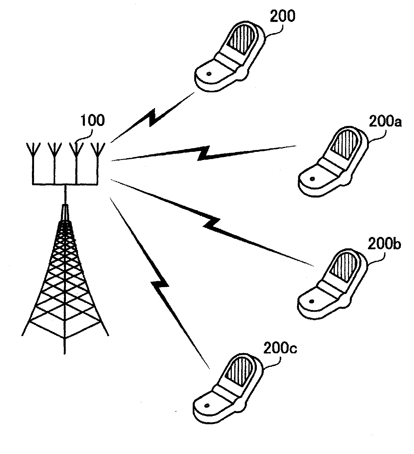
[0051] figure 2 It is a figure which shows the system structure of 1st Embodiment. The mobile communication system according to the first embodiment is a wireless communication system in which a wireless base station performs wireless communication with a plurality of mobile stations. This radio communication system includes a radio base station 100 and mobile stations 200, 200a, 200b, and 200c.

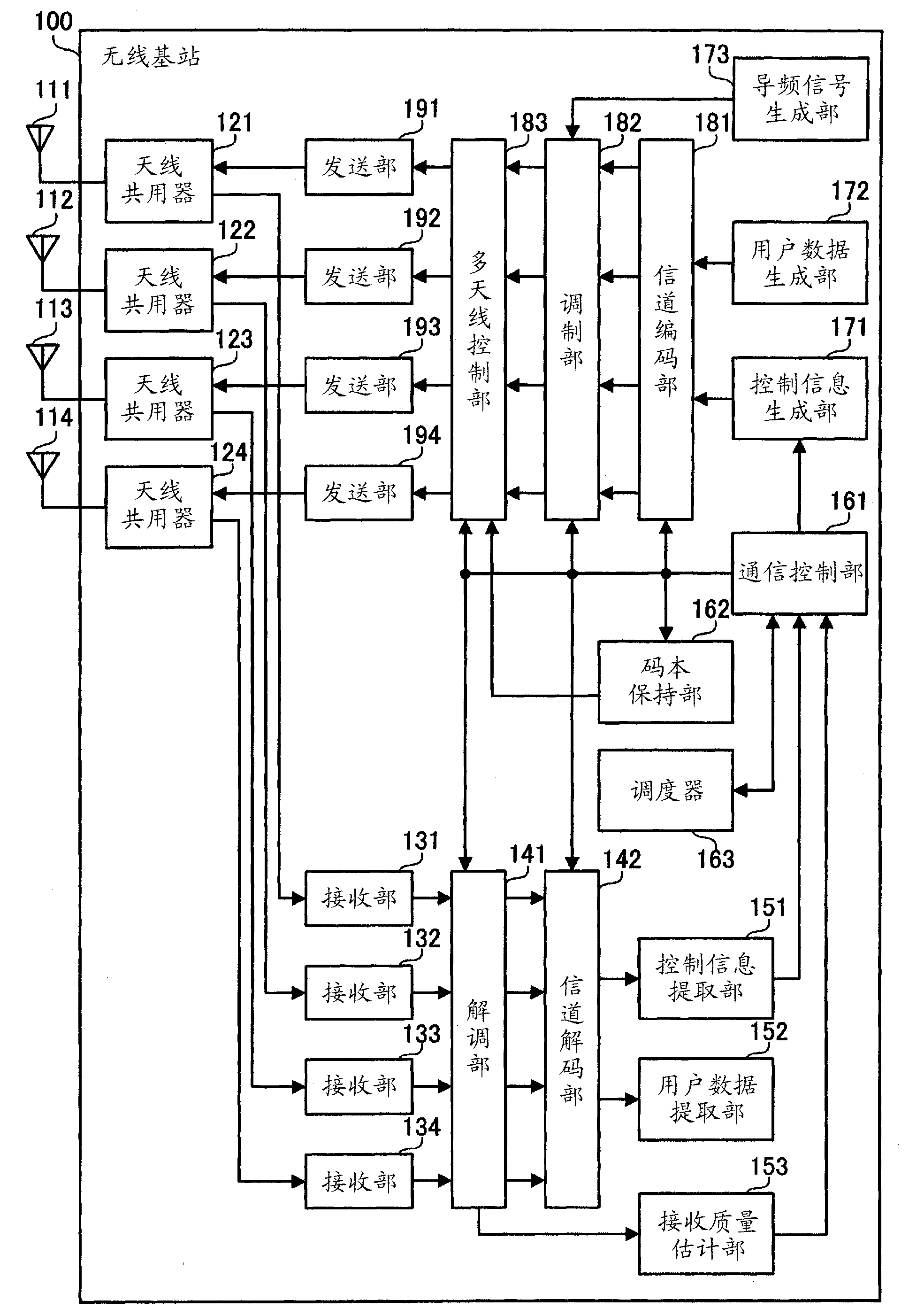
[0052] The radio base station 100 is a communication device that relays packet data between mobile stations 200 , 200 a , 200 b , and 200 c located within a range (cell) of radio waves and a mobile station of a communication partner. The radio base station 100 has four transmitting and receiving antennas. The radio base station 100 performs multi-antenna communication based on the precoding MIMO method with the mobile stations 200, 200a, 200b, and 200c using these four transmission and...

no. 2 Embodiment approach

[0141] Next, a second embodiment will be described in detail with reference to the drawings. The description will focus on the differences from the above-mentioned first embodiment, and the description of the same matters will be omitted.

[0142] Figure 10 It is a figure which shows the system structure of 2nd Embodiment. Like the first embodiment, the mobile communication system of the second embodiment is a wireless communication system in which a wireless base station performs wireless communication with a plurality of mobile stations. This radio communication system includes a radio base station 300 and mobile stations 400, 400a, 400b, and 400c.

[0143] The functions of the radio base station 300 and the mobile stations 400, 400a, 400b, and 400c are basically the same as those of the radio base station 100 and the mobile stations 200, 200a, 200b, and 200c of the first embodiment. However, the radio base station 300 can form four orthogonal directional beams using fou...


PUM


Abstract

The invention discloses a receiving device and a transmitting device. The receiving device comprises a receiving part, a control part and a transmitting part, wherein the receiving part is used for receiving information transmitted from the transmitting device and related with weight vectors; the control part is used for selecting proper weight vectors from all the weight vectors under the condition that assignment of candidates of the weight vectors and assignment of the weight vectors do not exist in the information related with the weight vectors, selecting proper weight vectors from the weight vectors assigned as the candidates under the condition that the assignment of the candidates of the weight vectors exists in the information related with the weight vectors, and selecting the assigned weight vectors under the condition that the assignment of the weight vectors exists in the information related with the weight vectors; and the transmitting part is used for transmitting the weight vectors selected by the control part and quality information aiming at the selected weight vectors to the transmitting device.

Description

[0001] The patent application of the present invention is the title of the invention "transmission device, transmission control method and communication device", the application date is December 05, 2007, the international application number is "PCT / JP2007 / 073465", and the national application number is "200780101784.5". A divisional application of an invention patent application. technical field [0002] The present invention relates to a transmission device, a transmission control method, and a communication device, and more particularly, to a transmission device that wirelessly transmits a transmission signal using a plurality of antennas, a transmission control method, and a communication device that receives the transmission signal. Background technique [0003] Currently, wireless communication systems such as mobile phone systems and wireless LANs (Local Area Networks) are widely used. In addition, in order to cope with the increase in access to the Internet and the u...

Claims


Application Information

Patent Timeline
Patent Type & Authority Applications(China)
IPC IPC(8): H04B7/06
Inventor 渡边真弘
Why Eureka
Try Eureka