Digital pneumatic quantitative glue injection system

A technology of glue injection and glue injection tube, which is applied in the direction of coating, liquid coating device on the surface, etc., can solve the problems of time-consuming and laborious, troublesome glue injection, poor control of glue injection volume, etc., and achieve high efficiency and high glue injection quality Good results

Inactive Publication Date: 2013-06-26
大连四达高技术发展有限公司
View PDF5 Cites 3 Cited by
  • Summary
  • Abstract
  • Description
  • Claims
  • Application Information

AI Technical Summary

Problems solved by technology

The glue injection mechanism of this structure is very random, the amount of glue injection is not easy to control, the glue injection is troublesome, time-consuming and laborious, and the efficiency is low. After the glue is injected, the appearance effect is poor, and manual inspection is required.

Method used


Image

  • Digital pneumatic quantitative glue injection system

Examples


Embodiment Construction

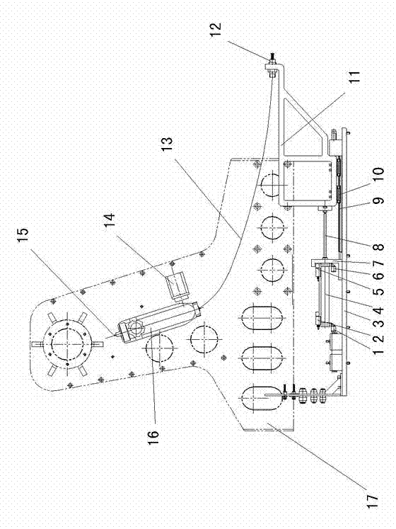
[0007] like figure 1 Shown: 17 is the frame, 16 is the rubber tube, and the rubber tube 16 is fixedly connected on the frame 17. The outlet of the glue cartridge 16 is connected with the glue spray nozzle 12 through the glue injection pipe 13 .

[0008] A base plate 3 is fixed below the frame 17, and a cylinder 4 connected to the pneumatic device is fixedly installed on the base plate 3 through a bracket 7. One end of the cylinder 4 has a left connection port 1, and the other end has a right connection port 6. The pneumatic device passes through The left connection port 1 and the right connection port 6 are connected with the cylinder 4 . One end above the cylinder 4 has a left position switch 2 connected with the electric control device, and the other end has a right position switch 5 connected with the electric control device.

[0009] The outer end of the piston rod 8 matched with the cylinder 4 is connected with a mobile frame 11, the base plate 3 is fixed with a slidewa...


PUM


Abstract

The invention discloses a digital pneumatic quantitative glue injection system which comprises a glue cylinder. An outlet of the glue cylinder is connected with a glue nozzle through a glue injection pipe; the glue cylinder is fixedly connected to a frame; a bottom plate is fixed below the frame; a cylinder is arranged on the bottom plate; a moving rack is connected with the outer end of a piston rod matched with the cylinder; a slideway is formed between the moving rack and the bottom plate; the glue nozzle is mounted at the front end of the moving rack; and a cavity in the rear part of a glue pushing piston inside the glue cylinder is connected with a pneumatic control device comprising a quantitative valve through an air pipe connecting port. The glue injection mechanism has the advantages of high accuracy, timeliness, quantification, high glue injection quality and high efficiency and is free of checking during glue injection.

Description

technical field [0001] The invention relates to a glue injection mechanism, in particular to a digital pneumatic quantitative glue injection system. Background technique [0002] In the process of aircraft manufacturing and assembly, some parts need to be partially injected with glue. At present, manual glue injection is used. The glue injection tools include rubber cartridges. There is a glue injection pipe connected to the front outlet of the glue cartridge. The glue injection pipe is connected to the nozzle. There is a piston inside, and the push rod connected with the piston rod pushes the piston forward to achieve the purpose of glue injection. The glue injection mechanism of this structure is very random, the amount of glue injection is not easy to control, the glue injection is troublesome, time-consuming and laborious, the efficiency is low, and the appearance effect after glue injection is poor, and manual inspection is required. Contents of the invention [0003...

Claims


Application Information

Patent Timeline
Patent Type & Authority Applications(China)
IPC IPC(8): B05C5/02B05C11/10
Inventor 李东栓
Owner 大连四达高技术发展有限公司
Why Eureka
Try Eureka