Tension control and torsion spring steel coil brake device for spindle of braiding machine

A tension control and braking device technology, applied in the field of knitting machines, can solve the problems of unstable braking force, easy wear of friction plates, large braking stroke, etc., and achieve the effect of large braking torque, short braking stroke and sensitive braking

Active Publication Date: 2013-06-26
浙江本发科技有限公司
View PDF12 Cites 7 Cited by
  • Summary
  • Abstract
  • Description
  • Claims
  • Application Information

AI Technical Summary

Problems solved by technology

Existing knitting machines are still very imperfect in this respect, for example, the attached The spindle brake mechanism of the prior art shown in Figure 1 relies on the pull rod to push the pendulum and uses the friction plate to brake the spindle chassis. However, the friction plate is easy to wear, the life is short, and the braking force is unstable after oil seeps into it. Easy to slip, insensitive to response, large braking stroke

Method used


Image

  • Tension control and torsion spring steel coil brake device for spindle of braiding machine
  • Tension control and torsion spring steel coil brake device for spindle of braiding machine
  • Tension control and torsion spring steel coil brake device for spindle of braiding machine

Examples


Embodiment 1

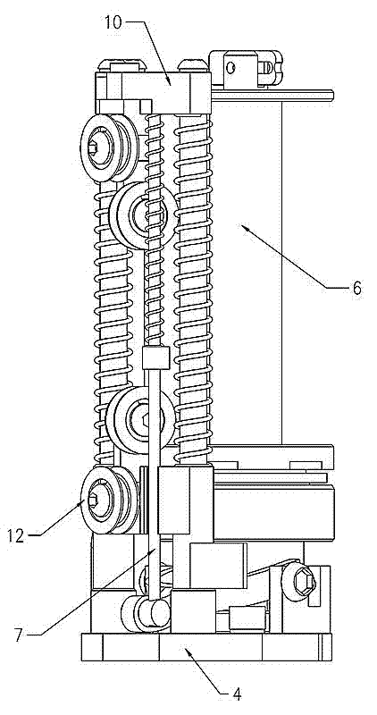
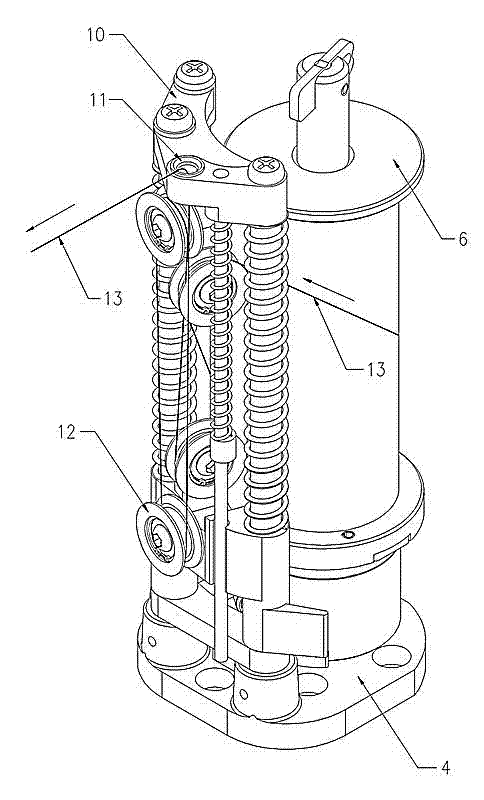
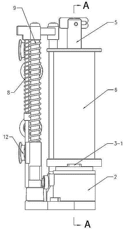
[0029] The structure of the tension control of the spindle of the braiding machine and the braking device of the torsion spring steel coil is as follows: figure 2 - Figure 9 As shown, it includes: steel coil torsion spring 1, elastic sleeve 2, shaft support 3, base 4, central shaft 5, spindle 6, pull rod 7, small spring 8, large spring 9, upper frame 10;

[0030] see Figure 5 - Figure 7 , the upper torsion arm 1-1 of the steel coil torsion spring 1 is in a horizontal direction, inserted into the upper gap 2-1 of the elastic sleeve; the lower torsion arm 1-2 is vertically arranged, and inserted into the step gap of the central axis 5; The helical inner diameter of the torsion spring 1 is the same as the lower end of the shaft 3 and the outer diameter of the step of the central shaft 5. In the free state, the inner wall of the steel coil torsion spring 1 wraps tightly the outer walls of the shaft 3 and the central shaft 5 at the same time, showing a braking state. . The ...


PUM


Abstract

A tension control and torsion spring steel coil brake device for a spindle of a braiding machine comprises a steel coil torsion spring, an elastic sleeve, a drill axis, a base and a central shaft, wherein a torque arm above the steel coil torsion spring is inserted in a notch on the elastic sleeve, and a torque arm below the steel coil torsion spring is inserted in a notch of the central shaft; under a free state, the inner wall of the steel coil torsion spring wraps up the outer walls of the drill axis and the central shaft, and a gap is reserved between the elastic sleeve and the steel coil torsion spring, so that the elastic sleeve and the steel coil torsion spring can rotate relatively; a rolling wheel is arranged on a bulge at the upper end of the elastic sleeve, and the circumferential profile of the rolling wheel is closely attached on a wedge of a draw bar; and when the machine is stopped, the tension of braiding wires disappears instantly, the draw bar drops on the base under the action of the spring, during descending, the wedge pushing the rolling wheel is loosen, the elastic sleeve restores rotationally, the steel coil torsion spring returns back to be in a free state, the inner diameter of the helix also wraps up the outer walls of the central shaft and the drill axis, and a lug on the drill axis clamps the spindle to enable the spindle to stop rotating instantly. The tension control and torsion spring steel coil brake device adopts a band-type brake to brake, so that the braking operation is flexible and reliable.

Description

technical field [0001] The invention relates to the technical field of braiding machines, in particular to tension control of a braiding machine spindle and a torsion spring coil braking device. Background technique [0002] High-pressure oil hoses, gas hoses, cable hoses, etc., and even water hoses for bathrooms, all need to be braided with a protective layer on the outer layer, and braided wires such as metal wires or nylon wires are wound into a net. The general structure of our country's knitting machine is that there are more than 20 spindles walking on the panel around the central hose in an S-shaped trajectory, and the braiding wire is wound on the central hose during the process. The weaving process requires the spindles to flow continuously , Supply the braiding yarn with constant tension. If the yarn of one of the spindles is used up or broken, the whole machine will automatically shut down. . When the power is suddenly cut off, all the spindles with silk will c...

Claims


Application Information

Patent Timeline
Patent Type & Authority Applications(China)
IPC IPC(8): D04C3/40
Inventor 梁贤军梁宽薛林晓万春明
Owner 浙江本发科技有限公司
Why Eureka
Try Eureka