
Constant tension numerical control multi-thread square cutting machine without pressure sensor

A technology of pressure sensor and constant tension, which is applied in the field of constant tension control CNC multi-wire square cutting machine, can solve the problems of unstable tension control, reduced cutting efficiency, and high separation cost, and achieve fast loading and unloading, stable cutting speed, and high tension The effect of small fluctuation range

Active Publication Date: 2013-09-11
海宁市日进科技有限公司
View PDF5 Cites 0 Cited by
  • Summary
  • Abstract
  • Description
  • Claims
  • Application Information

AI Technical Summary

Problems solved by technology

But at present, the multi-wire cutting technology still has the problem that the knife loss of multi-wire cutting accounts for a large proportion of the material processing loss, which can reach more than 50%; Decreased efficiency; unstable tension control and other defects

Method used

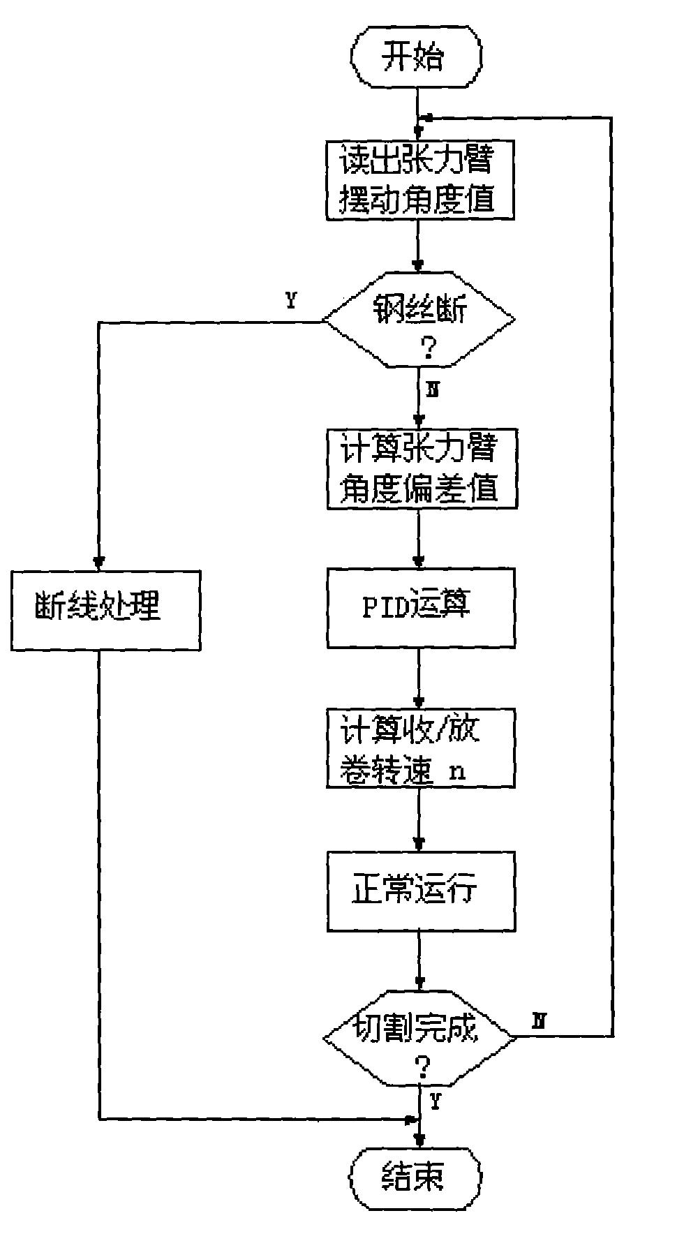
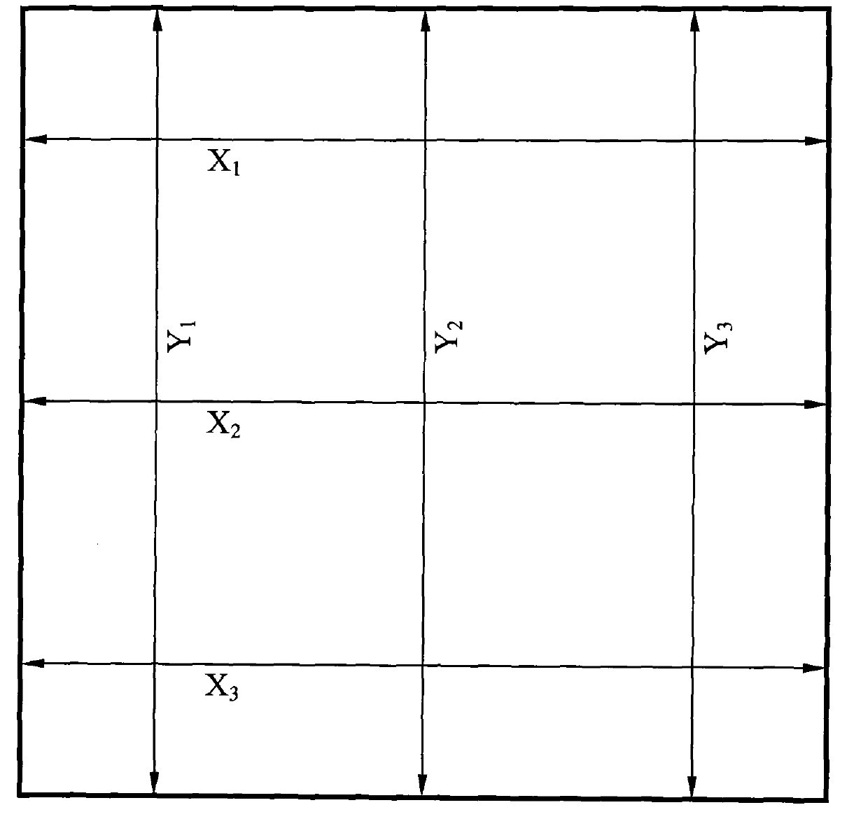

Image

  • Constant tension numerical control multi-thread square cutting machine without pressure sensor
  • Constant tension numerical control multi-thread square cutting machine without pressure sensor
  • Constant tension numerical control multi-thread square cutting machine without pressure sensor

Examples


Embodiment 1

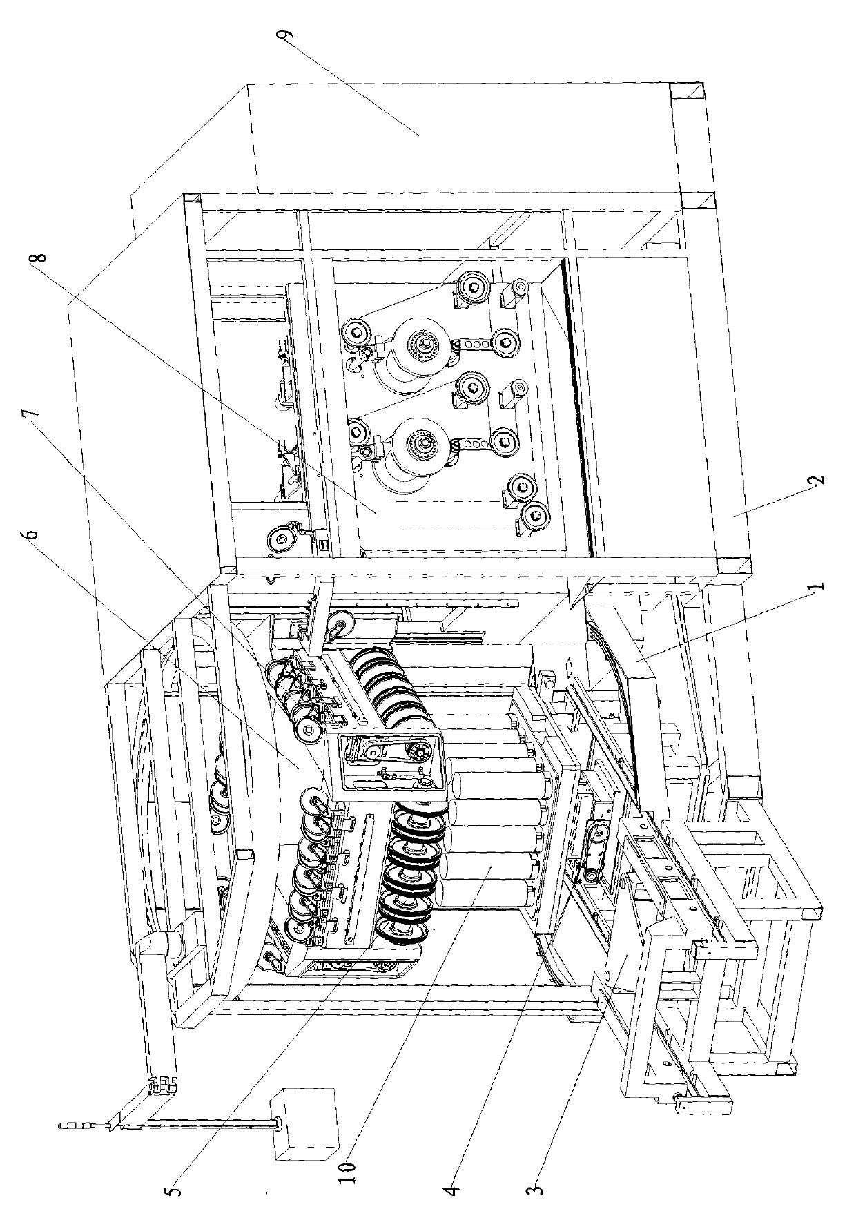
[0071] A constant tension control CNC multi-wire square cutting machine without a pressure sensor, including a chassis 1, a frame 2, a trolley 3, a workbench 4, a cutting roller 5, a cutting head frame 6, a guide wheel 7, and wire winding Department 8, electrical cabinet 9, such as figure 1 As shown, the specific structure is: there are two slide rails on the chassis 1, the trolley 3 is placed on the slide rails, the workbench 4 is fixed between the slide rails, the frame 2 is fixed behind the chassis 1, and the cutting head is above the workbench 4 Frame 6, the cutting head frame 6 is fixed on the crossbeam of the frame 2, the cutting roller 5 is fixed under the cutting head frame 6, the servo motor is installed in the cutting head frame 6, and the cutting spindle and the tangent wheel are driven to rotate through the V-ribbed belt transmission, cutting The wire is introduced by the wire winding part 8 through the importing wire wheel, and is exported to the wire winding part...

Embodiment 2

[0131] A constant tension control numerically controlled multi-wire square cutting machine without a pressure sensor. The cutting roller 5 is engraved with ten V-shaped grooves, and the cutting wires are embedded in the V-shaped grooves. The other structures are the same as in Embodiment 1.


PUM


Abstract

The invention relates to the field of plate cutting machines, in particular to a constant tension numerical control multi-thread square cutting machine without a pressure sensor. The constant tension numerical control multi-thread square cutting machine without the pressure sensor comprises a base plate, a frame, a trolley, a workbench, a cutting roller, a cutting headstock, a thread guide wheel, a filament arranging and winding part and an electric appliance cabinet and is characterized in that: the base plate is provided with two slide rails; the trolley is arranged on the slide rails; the workbench is fixed between the slide rails; the frame is fixed behind the base plate; the cutting headstock is arranged above the workbench and is fixed on the beam of the frame; the cutting roller is fixed below the cutting headstock; the filament arranging and winding part is connected to the rear part of the cutting roller and is fixed on the base of the frame; a cutting filament is connected with a winding wheel and the cutting roller of the filament arranging and winding part; and the electric appliance cabinet is fixed behind the frame. The machine is a silicon chip cutting machine with high machining capability, high machining accuracy and high material utilization rate.

Description

technical field [0001] The invention relates to the field of plate cutting machinery, in particular to a constant tension control numerically controlled multi-wire square cutting machine without a pressure sensor. Background technique [0002] Wafer cutting is the upstream key technology for the production of crystalline silicon wafers, the leading material in the solar photovoltaic industry. The quality and scale of cutting directly affect the subsequent production of the entire industrial chain. With the rapid development of my country's photovoltaic power generation and information industry, especially the microelectronics industry, the demand for silicon wafers is increasing, the diameter of processed workpieces is increasing, and the technical requirements for processed products are also increasing. At present, silicon wafer slicing mostly adopts inner circle cutting and multi-wire cutting with free abrasive grains. Internal cutting is a traditional processing method, ...

Claims


Application Information

Patent Timeline
Patent Type & Authority Patents(China)
IPC IPC(8): H01L21/301B28D5/04
Inventor 卢建伟
Owner 海宁市日进科技有限公司
Learn More